Watson-Marlow MM440 User Manual
Micromaster 440
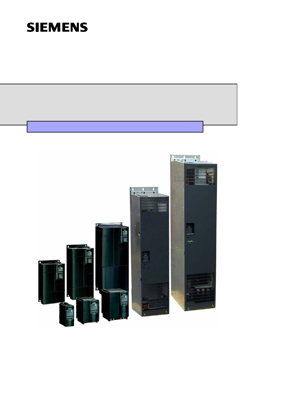
Table of contents
Document Outline
- Foreword
- Definitions and Warnings
- Safety Instructions
- Electrostatic Sensitive Devices (ESD)
- Table of Contents
- 1 Overview
- 2 Installation
- 3 Functions
- 3.1 Parameters
- 3.2 Operator panels for MICROMASTER
- 3.3 Block diagram
- 3.4 Factory setting
- 3.5 Commissioning
- 3.5.1 50/60 Hz setting
- 3.5.2 Motor circuit
- 3.5.3 Quick commissioning
- 3.5.4 Calculating the motor / control data
- 3.5.5 Motor data identification
- 3.5.6 Magnetizing current
- 3.5.7 Commissioning the application
- 3.5.7.1 Serial Interface (USS)
- 3.5.7.2 Selection of command source
- 3.5.7.3 Digital input (DIN)
- 3.5.7.4 Digital output (DOUT)
- 3.5.7.5 Selection of frequency setpoint
- 3.5.7.6 Analog input (ADC)
- 3.5.7.7 Analog output (DAC)
- 3.5.7.8 Motor potentiometer (MOP)
- 3.5.7.9 Fixed frequency (FF)
- 3.5.7.10 JOG
- 3.5.7.11 Ramp function generator (RFG)
- 3.5.7.12 Reference/limit frequencies
- 3.5.7.13 Inverter protection
- 3.5.7.14 Motor protection
- 3.5.7.15 Encoder
- 3.5.7.16 V/f control
- 3.5.7.17 Field-orientated control
- 3.5.7.18 Converter-specific Functions
- 3.5.7.19 Command and drive data set
- 3.5.7.20 Diagnostic parameters
- 3.5.7.21 End of commissioning
- 3.5.8 Series commissioning
- 3.5.9 Parameter reset to the factory setting
- 3.6 Inputs / outputs
- 3.7 Communications
- 3.8 Fixed frequencies (FF)
- 3.9 Motorized potentiometer (MOP)
- 3.10 JOG
- 3.11 PID controller (technological controller)
- 3.12 Setpoint channel
- 3.13 Free function blocks (FFB)
- 3.14 Motor holding brake (MHB)
- 3.15 Electronic brakes
- 3.16 Automatic restart
- 3.17 Flying restart
- 3.18 Closed-loop Vdc control
- 3.19 Positioning down ramp
- 3.20 Monitoring functions / messages
- 3.21 Thermal motor protection and overload responses
- 3.22 Power module protection
- 3.23 Open-loop/closed-loop control technique
- 4 Troubleshooting
- 5 MICROMASTER 440 specifications
- 6 Options
- 7 Electro-magnetic compatibility (EMC)
- Appendices