Watson-Marlow MM440 User Manual
Page 203
Issue 10/06
3 Functions
MICROMASTER 440 Operating Instructions
6SE6400-5AW00-0BP0
203
The DC brake can therefore support a braking operation from approx. < 10 Hz or
prevents / minimizes the increase in the DC link voltage for regenerative braking.
This is realized because energy is directly absorbed in the motor. The essential
advantage and the main application of the DC brake is the fact that a holding
torque can be generated at standstill (0 Hz). For instance, this is important for
applications where after positioning, any motion in the mechanical system / product
itself can result in waste.
DC braking is especially used for:
¾
Centrifuges
¾
Saws
¾
Grinding machines
¾
Conveyor belts
Sequence
ℵ
1. Enabled using P1233
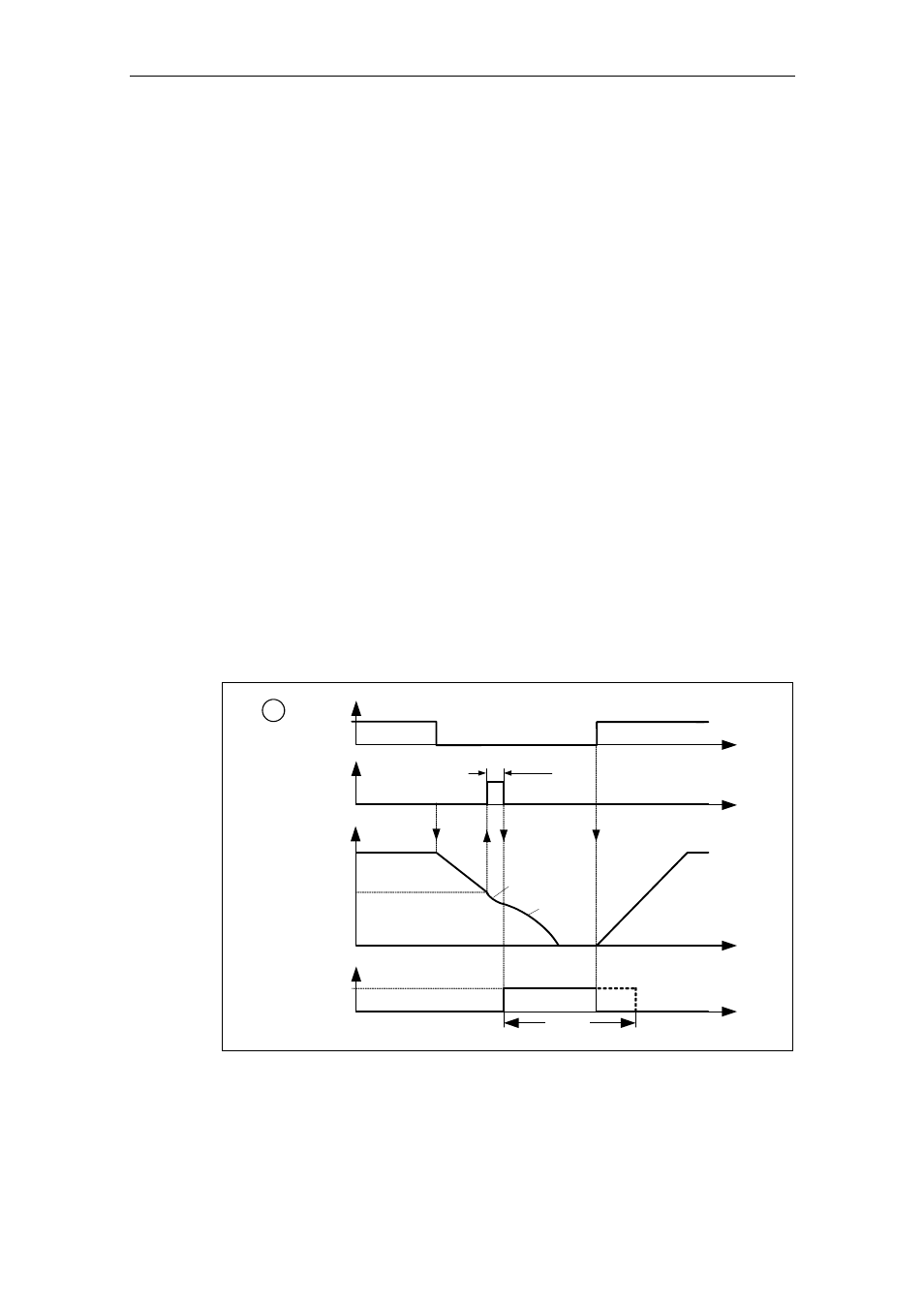
2. DC braking is activated with the OFF1 or OFF3 command (refer to Fig. 3-73)
3. The drive inverter frequency is ramped-down along the parameterized OFF1 /
OFF3 ramp down to the frequency at which DC braking is to start - P1234. This
means that the kinetic energy of the motor can be reduced without endangering
the drive. However, if the ramp-down time is too short, there is a danger that a
fault will be output as a result of an overvoltage condition in DC link - F0002.
4. The inverter pulses are inhibited for the duration of the de-magnetizing time
P0347.
5. The required braking current P1233 is then impressed for the selected braking
time P1232. The status is displayed using signal r0053 bit 00.
The inverter pulses are inhibited after the braking time has expired.
t
P1234
OFF1/OFF3
ON
t
t
?f?
P1233
1
tt
P0347
OFF2
DC braking
OFF2
0
1
DC braking active
r0053
Bit 00
Fig. 3-73
DC braking after OFF1 / OFF3