Watson-Marlow MM440 User Manual
Page 128
3 Functions
Issue 10/06
MICROMASTER 440 Operating Instructions
128
6SE6400-5AW00-0BP0
DIN4
Terminals
Sequence control
BOP
P0700[0] = 2
P0700[1] = 1
P0810 = 722.3
ADC
Setpoint
channel
MOP
0
1
P1000[0] = 2
P1000[1] = 1
Motor
control
0
1
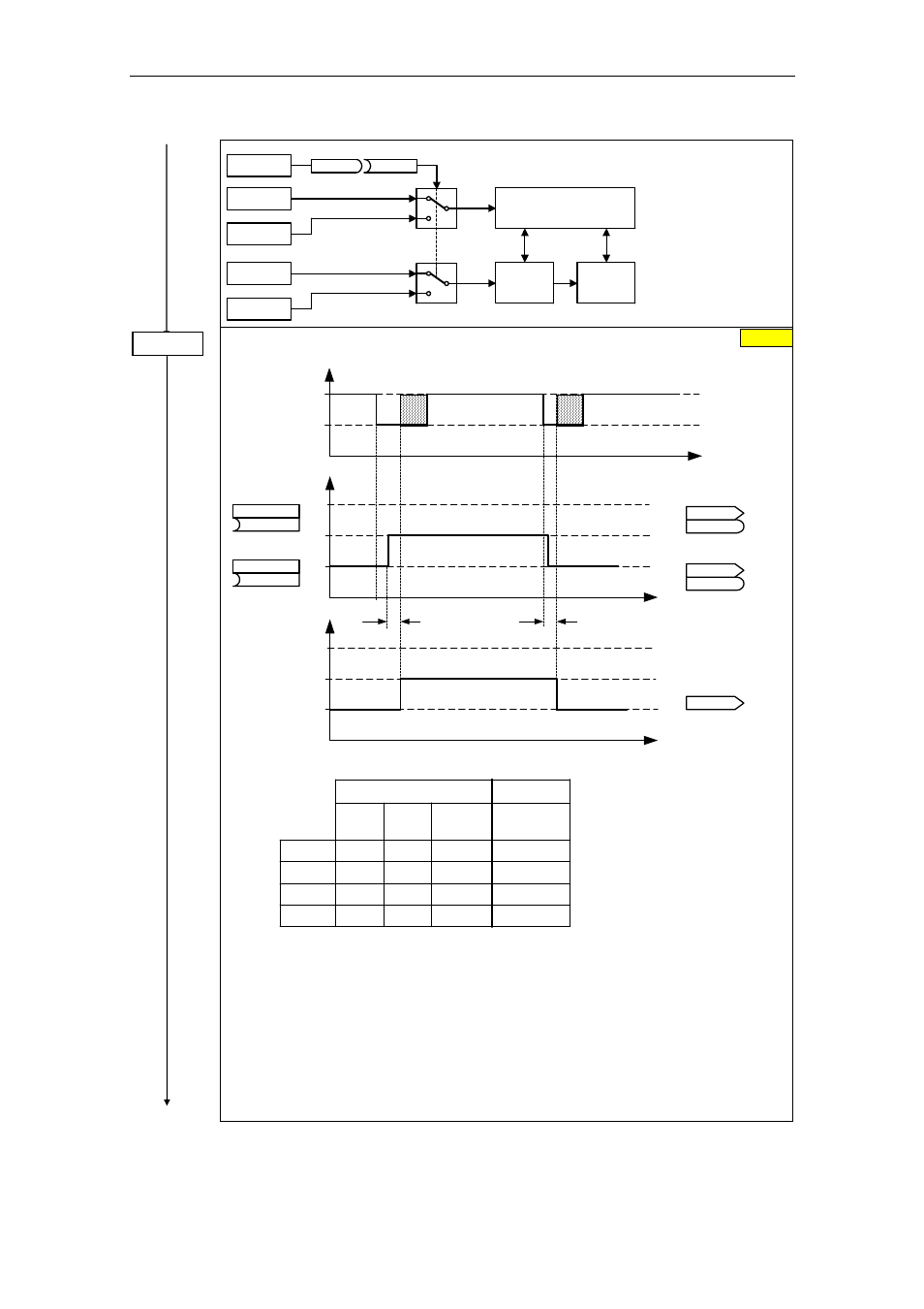
Drive data set (DDS) bit 0
Selects the command source from which bit 0 should be read-out to select a drive data set.
t
0
1
2
3
(0:0)
BI: DDS bit 0
P0820
(0:0)
BI: DDS bit 1
P0821
t
0
1
2
3
CO/BO: Act CtrlWd2
r0055
r0055
CO/BO: Act CtrlWd2
r0055
r0055
.04
.04
.05
.05
r0051[1]
Active DDS
Select DDS
approx. 50 ms
approx. 50 ms
Changeover time
Changeover time
Operation
Ready
t
r0051 [2]
CO: Active DDS
.01
The currently active drive data set (DDS) is displayed using parameter r0051[1]:
r0055
bit05
r0054
bit04
1. DDS
0
0
2. DDS
0
1
3. DDS
1
0
3. DDS
1
1
r0051 [0]
0
1
2
2
r0051 [1]
0
1
2
2
Select
DDS
Active
DDS
Most frequent settings:
722.0 = Digital input 1 (P0701 must be set to 99, BICO)
722.1 = Digital input 2 (P0702 must be set to 99, BICO)
722.2 = Digital input 3 (P0703 must be set to 99, BICO)
722.3 = Digital input 4 (P0704 must be set to 99, BICO)
722.4 = Digital input 5 (P0705 must be set to 99, BICO)
722.5 = Digital input 6 (P0706 must be set to 99, BICO)
722.6 = Digital input 7 (via analog input 1, P0707 must be set to 99)
722.7 = Digital input 8 (via analog input 2, P0708 must be set to 99)
0
P0820 = ...