Hoisting gear applications, 30 v dc / 5 a, Relay output via an additional relay – Watson-Marlow MM440 User Manual
Page 201
Issue 10/06
3 Functions
MICROMASTER 440 Operating Instructions
6SE6400-5AW00-0BP0
201
If the frequency inverter directly controls the motor holding brake using the
relay integrated in the frequency inverter, then the max. load capability of
this relay should be carefully taken into consideration in conjunction with the
voltage/current data of the holding brake. The following applies for the relay
integrated in the frequency inverter:
−
30 V DC / 5 A
−
250 V AC / 2 A
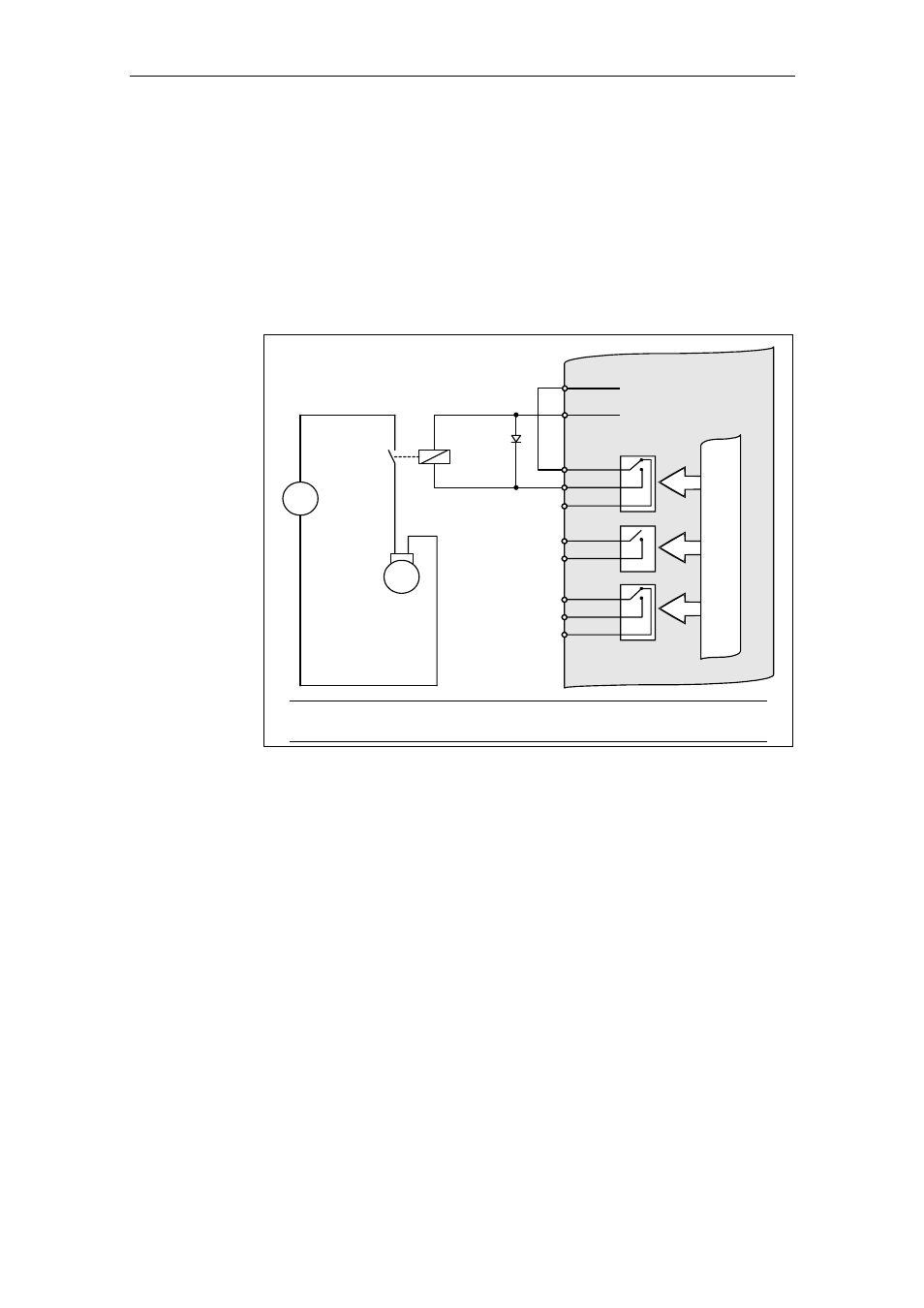
If this value is exceeded, an additional relay should, for example, be used.
♦ Indirectly connecting 1
st
relay output via an additional relay
Motor with
motor
holding brake
COM
NC
NO
COM
NC
NO
COM
NO
20
18
19
25
23
24
22
21
9
28
Output 0 V, max. 100 mA
(isolated)
Output +24 V, max. 100 mA
(isolated)
CPU
Surge
absorber
diode
24 V
0 V
Relay
MICROMASTER 440
M
3
~
=
Caution
The relay may not overload the internal 24 V power supply!
Fig. 3-71
Indirect motor holding brake connection
Hoisting gear applications
For high loads and low mechanical friction, especially when lowering a load, energy
is regenerated that can cause the DC link voltage to increase. This increase can be
prevented using dynamic braking (refer to Section 3.15.3; P1237).
In order that there is no negative effect when using dynamic braking, the following
functions should be disabled for hoisting gear applications:
♦ Vdc_max controller P1240
♦ Compound brake P1236