Watson-Marlow MM440 User Manual
Page 209

Issue 10/06
3 Functions
MICROMASTER 440 Operating Instructions
6SE6400-5AW00-0BP0
209
Chopper
control
B-
B+
R
P1237 = 1
(5 %)
Chopper
control
B-
B+
R
P1237 = 3
(20 %)
R
R
R
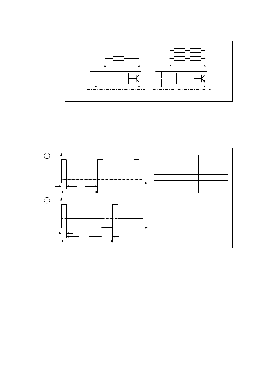
Fig. 3-79
Increasing the level of braking energy which can be absorbed
The continuous power and the load duty cycle are modified using parameter P1237
(setting values, refer to Fig. 3-80a). If the load duty cycle monitoring switches from
the peak power (100%) to the continuous power, then this is dissipated for an
unlimited length of time in the braking resistor (refer to Fig. 3-80b). Contrary to the
braking resistor, as listed in Catalog DA51.2, the chopper control can be
permanently operated with 100% power.
t
t
cycle
P
DB
P
100
t
ON
t
OFF
P1237
t
ON
t
OFF
t
cycle
P
DB
5 %
12.0
228.0
240.0
0.05
10 %
12.6
114.0
126.6
0.10
20 %
14.2
57.0
71.2
0.20
50 %
22.8
22.8
45.6
0.50
100 % Infinite
0 Infinite
1.00
t
t
cycle
P
DB
P
100
t
100
t
P1237
t
OFF
a
b
Fig. 3-80
Chopper load duty cycle
For MICROMASTER 440, up to and including Size FS F, the braking module is
integrated in the drive inverter and the braking resistor can be connected via
external terminals B+, B-.
