Commissioning steps – Watson-Marlow MM440 User Manual
Page 224
3 Functions
Issue 10/06
MICROMASTER 440 Operating Instructions
224
6SE6400-5AW00-0BP0
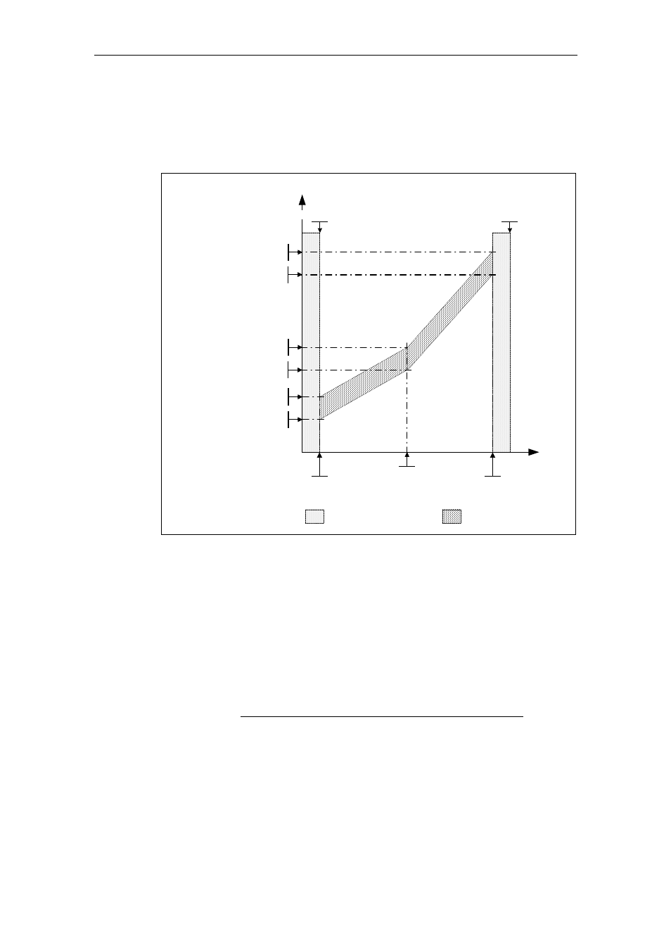
The frequency/torque tolerance bandwidth is defined by the gray shaded area in
Fig. 3-89. The bandwidth is determined by the frequency values P2182 – P2184
and the torque limits P2186 – P2189. When defining the tolerance bandwidth it
should be ensured that a specific tolerance is taken into account in which the
torque values are allows to vary corresponding to the application.
P2189
Upper torque threshold 3
P2190
Lower torque threshold 3
P2187
Upper torque threshold 2
P2188
Lower torque threshold 2
P2185
Upper torque threshold 1
P2186
Lower torque threshold 1
Boundary zones
De-activated monitoring
Envelope curve
Active monitoring
P2182
Threshold frequency 1
P2183
Threshold frequency 2
P2184
Threshold frequency 3
|Torque| [Nm]
|Frequency|
[Hz]
P1082
Max. frequency
P1080
Min. frequency
Fig. 3-89
Frequency/torque tolerance bandwidth
Commissioning steps
1. In order to define the position of the tolerance bandwidth, different
characteristics must be determined as a function of the required load torque
monitoring (P2181). A differentiation can be made between the following cases:
a) P181 = 1 / 4
Load torque monitoring to detect a broken belt, i.e. under fault conditions,
the actual load torque is below the permissible tolerance bandwidth. In this
case, the load torque characteristic with minimum permissible load should be
determined.