Watson-Marlow MM440 User Manual
Page 124
3 Functions
Issue 10/06
MICROMASTER 440 Operating Instructions
124
6SE6400-5AW00-0BP0
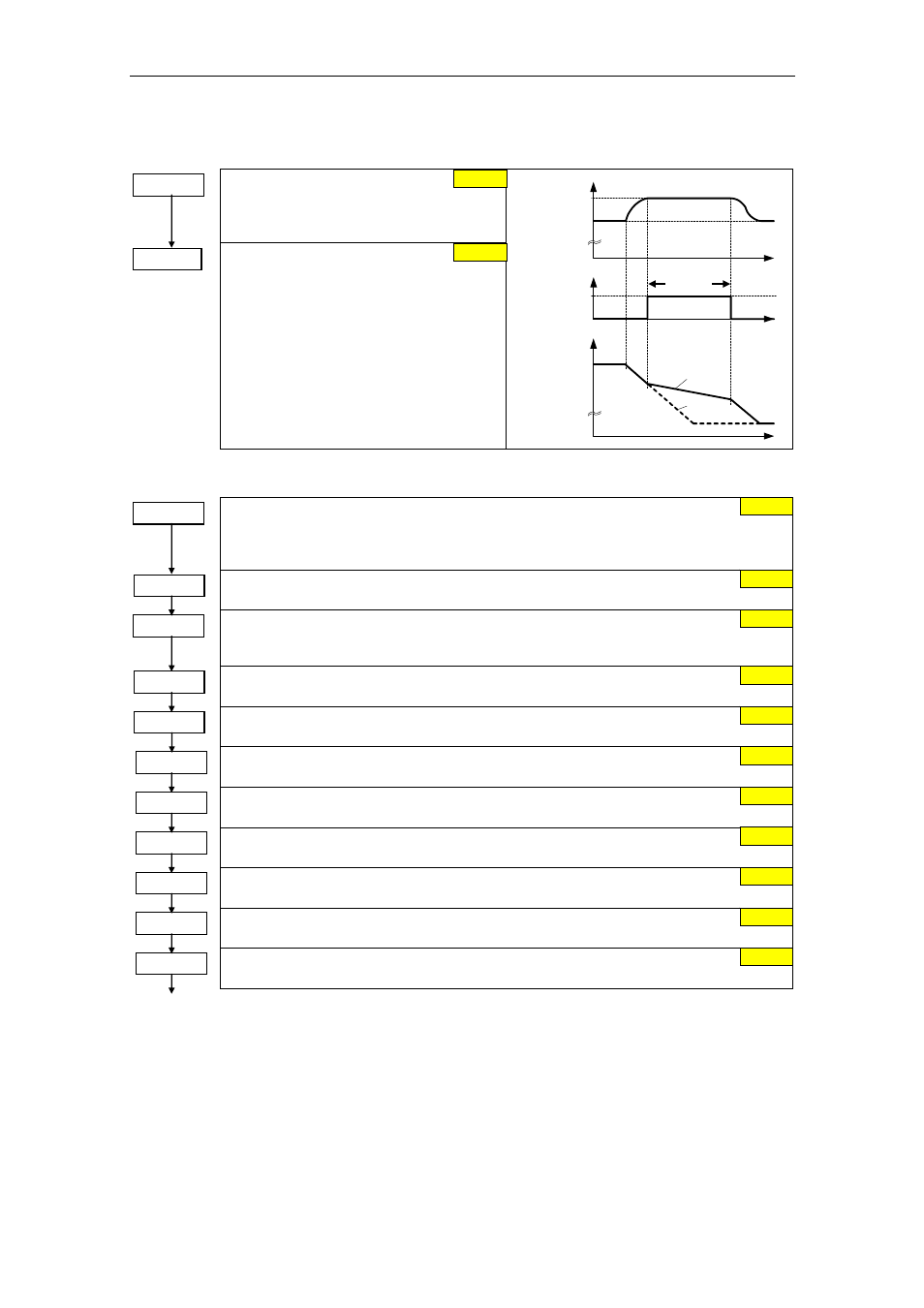
Vdc controller
P1240 =...
Configuration of Vdc controller
Enables / disables Vdc controller.
0 Vdc controller disabled
1 Vdc-max controller enabled
P1254 =...
Auto detect Vdc switch-on levels
Enables/disables auto-detection of switch-on
levels for Vdc control functionalities.
0 Disabled
1 Enabled
t
t
⏐f⏐
1
-controller active
V
DC_max
t
V
DC
0
r0056 Bit14
r1242
A0911
f
f
act
set
PID controller
P2200 =...
BI: Enable PID controller
PID mode Allows user to enable/disable the PID controller. Setting to 1 enables the PID
controller. Setting 1 automatically disables normal ramp times set in P1120 and P1121 and
the normal frequency setpoints.
P2253 =...
CI: PID setpoint
Defines setpoint source for PID setpoint input.
P2254 =...
CI: PID trim source
Selects trim source for PID setpoint. This signal is multiplied by the trim gain and added to
the PID setpoint.
P2257 =...
Ramp-up time for PID setpoint
Sets the ramp-up time for the PID setpoint.
P2258 =...
Ramp-down time for PID setpoint
Sets ramp-down time for PID setpoint.
P2264 =...
CI: PID feedback
Selects the source of the PID feedback signal.
P2267 =...
Max. value for PID feedback
Sets the upper limit for the value of the feedback signal in [%]..
P2268 =...
Min. value for PID feedback
Sets lower limit for value of feedback signal in [%]..
P2280 =...
PID proportional gain
Allows user to set proportional gain for PID controller.
P2285 =...
PID integral time
Sets integral time constant for PID controller.
P2291 =...
PID output upper limit
Sets upper limit for PID controller output in [%].
1
1
0.0
0.0
0.0
1.00 s
1.00 s
755.0
100.00 %
0.00 %
3.000
0.000 s
100.00 %