Figure 36, Mobile i/o user’s guide – Metric Halo 2882 operating guide User Manual
Page 51
Mobile I/O User’s Guide
43
powerful routing model to allow you to control the routing of signals
between physical & virtual inputs and the hardware mixer & physical out-
puts.
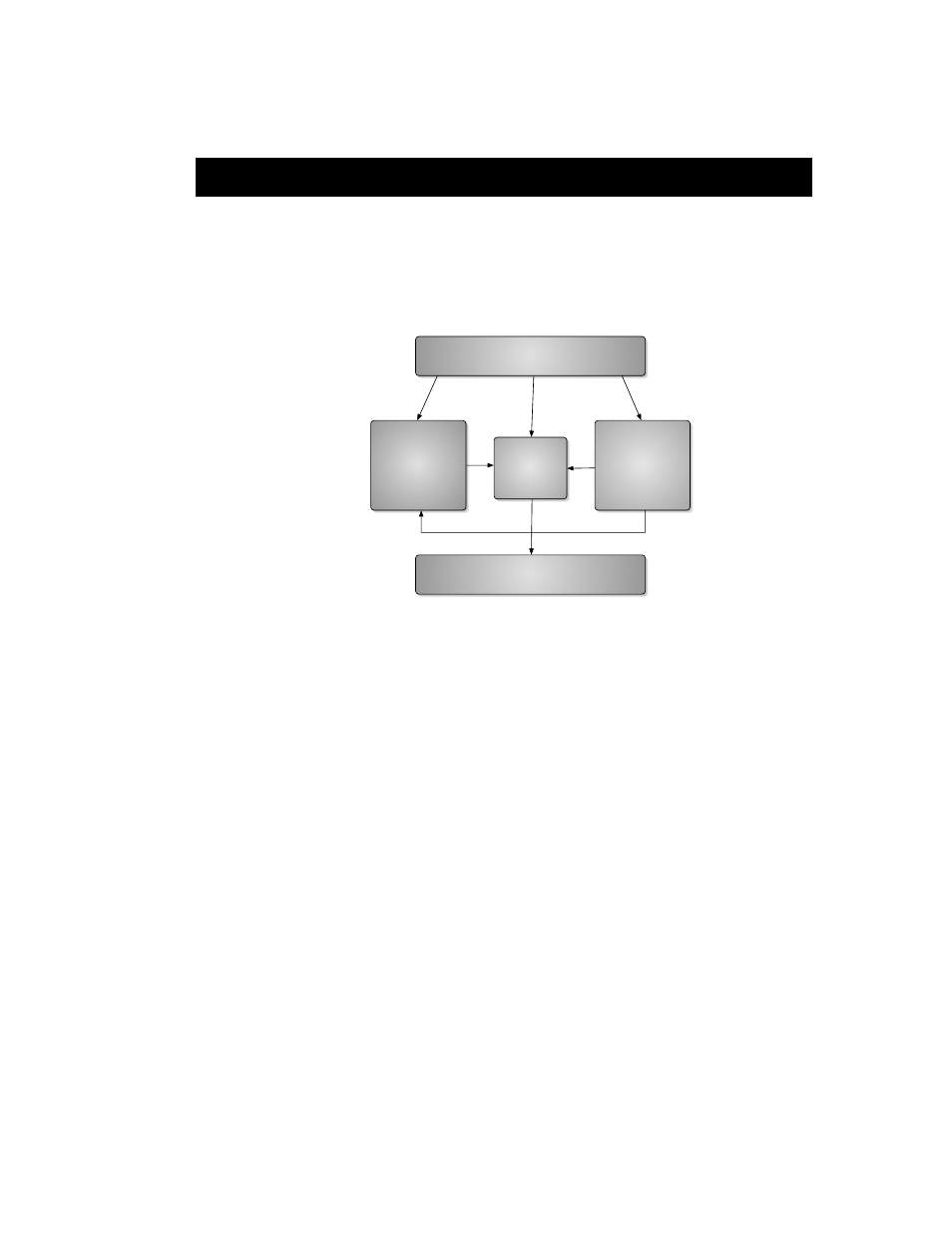
Conceptually, the architecture is quite simple:
All of the physical inputs (e.g. Analog, ADAT and Digital), all of the channels
being transmitted over the FireWire bus from the ASIO Application (e.g.
DAW), and all of the outputs from the Mobile I/O WIDE Mixer are available
to the Output Patchbay. The Output Patchbay can cross-point assign any of
its inputs to any of the physical outputs (e.g. Analog, ADAT and Digital).
All of the physical inputs and all of the channels being transmitted over the
FireWire bus from the ASIO Application are also inputs to the Mobile I/O
WIDE Mixer. Every bus has each of those inputs available for mixing. The
mixer outputs are sent to the Output Patchbay for routing to physical out-
puts. The number of mix busses varies with the Mobile I/O hardware model
and the sample rate. The Mobile I/O 2882 supports 10 mono (5 stereo) mix
busses at sample rates up to 50kHz (e.g. 1x rates) and 4 mono (2 stereo) mix
busses at sample rates up to 96kHz (e.g. 2x rates).
Every physical input is mult’ed from the router/mixer section and sent
directly over the FireWire bus to the ASIO host. Regardless of any mixing,
Figure 36: Block diagram of the Mobile I/O routing architecture
PHYSICAL INPUTS
PHYSICAL OUTPUTS
MIXER
ASIO APPLICATION
OUTPUT
PATCHBAY