Figure 27, Figure 28, Figure 29 – Metric Halo 2882 operating guide User Manual
Page 39: Mobile i/o user’s guide
Mobile I/O User’s Guide
31
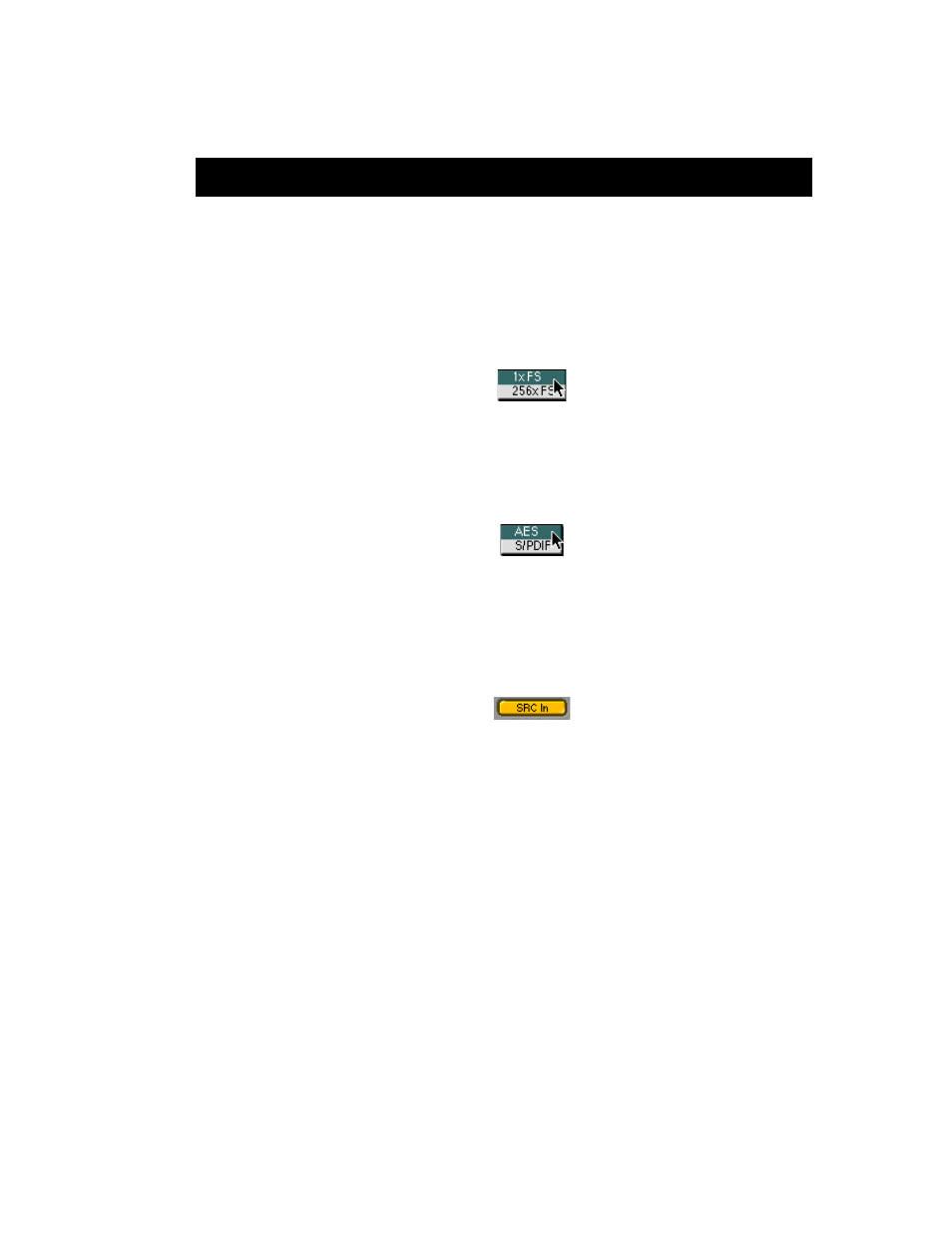
3. The WC Out popup menu allows you to select the output clock
signal the Mobile I/O generates on its WC Out BNC connector. The
available choices are 1x and 256x. The 1x signal is appropriate for
driving devices that accept a Word Clock signal. The 256x signal is
appropriate for driving devices that accept 256x or SuperClock sig-
nals. Refer to the documentation for the external device to deter-
mine what is the most appropriate clock reference for it.
4. The DI Source popup menu allows you to select the active input
for the digital input pair. The choices are AES and S/PDIF. This
selector physically switches the input to the digital audio receiver
between the RCA input and the XLR input.
5. The DI SRC button enables and disables the asynchronous sample
rate converter (SRC) in the Mobile I/O digital audio receiver. When
the SRC is engaged (button illuminated yellow), the digital audio
receiver will automatically synchronize the input signal to the
Mobile I/O system clock over a wide range of sample rate ratios.
This allows you to, for example, digitally transfer a sample from a
CD player into a 96k session without any clocking problems. If you
want to make bit-transparent transfers, you will need to disengage
the SRC and ensure that the Mobile I/O and the external device are
both using the same digital audio clock via one of the Mobile I/O
synchronization mechanisms.
6. The Lock indicators show which elements of the Mobile I/O clock-
ing system are properly locked. The clocking system must be
locked for the unit to behave as expected. If the system is not
locked, audio will play at the wrong rate and will be distorted or
noisy. Under normal circumstances, the system should always be
locked, but if you have selected an external clock source and the
Figure 27: WC Out Popup
Figure 28: DI Source Popup
Figure 29: DI SRC Buton