Onfiguration…… 6-10, Input channel configuration – Measurement Computing WavePort rev.3.0 User Manual
Page 62
6-10 WaveView
09-29-00
WavePort User’s Manual
Input Channel Configuration
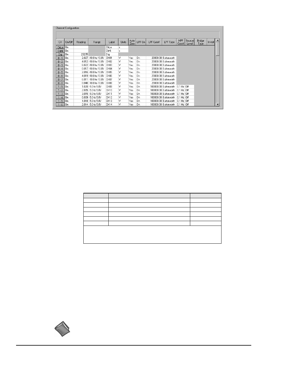
Channel Configuration Spreadsheet
The spreadsheet allows the analog input channels and/or digital channel to be configured and displayed.
The spreadsheet consists of rows and columns much like an accounting spreadsheet. The top few rows are
used for the high-speed digital input and other non-analog channels. The following rows (up to 72)
configure the analog input channels. The number of rows varies depending on system configuration.
The various columns contain the configuration information for each channel. Some columns allow blocks of
cells to be altered simultaneously, while others allow one cell to be changed at a time. Some columns may
be static and cannot be altered. Clicking a column header will select the entire column if applicable.
• CH. The channel number column labeled CH is static and cannot be altered. This column identifies the
analog (or digital) input channel to be configured in that row. This number includes all channel
numbers from the WaveBook and any attached expansion chassis (WBK10/10H/10A, WBK14,
WBK15, and WBK16). The channels are numbered as follows:
CH
Description
Default Label
CtrLo
WavePort External Clock Period (Lo)
CtrLo
CtrHi
WavePort External Clock Period (Hi)
CtrHi
Dig
WaveBook Digital Channel
Dig
0-1 to 0-8
WaveBook Analog Channels
CH01 to CH08
1-1 to 1-8
First set of Expansion Channels*
CH09 to CH16
2-1 to 2-8
Second set of Expansion Channels*
CH17 to CH24
*WavePort/PE units appear as a WaveBook with one WBK14 (PE8), or two WBK14s
(PE16).
*WavePort/V units will appear as a WaveBook with one WBK10A (V16), two
WBK10As (V24), or none (V8).
• On/Off. This column allows you to include or exclude a channel from the scan list. When a cell is
selected, the selection box above the spreadsheet allows “On” or “Off” to enable or disable the channel.
Double-clicking a cell in this column will toggle the channel status. The Make All Channels Active and
Make All Channels Inactive menu items under the Edit menu can be used to globally change all
channels to either “On” or “Off.”
• Reading. Not user configurable. This column displays values of enabled channels.
• Range. This column allows you to set the gain and polarity for the selected channel(s). Clicking the
mouse in any of the analog channel Range boxes brings up the "Select Range" selection box. The
range of gains available in the selection box depends on the hardware installed in the system. Double-
clicking on a channel’s Range box will cycle through the available ranges. The Range selections have
no effect on the Digital Input channel.
Reference Note:
Ranges are presented in Chapter 10, Specifications.