Cable driving, Wbk14 - specifications, Fk c v icc ib = − 2 – Measurement Computing WavePort rev.3.0 User Manual
Page 134
A-4
04-06-00
Using Accelerometers
Cable Driving
Operation over long cables is a concern with all types of sensors. Concerns involve cost, frequency
response, noise, ground loops, and distortion caused by insufficient current available to drive the cable
capacitance.
The cost of long cables can be reduced by coupling a short (1 m) adapter cable from the accelerometer to a
long low-cost cable like RG-58U or RG-62U with BNC connectors. Since cable failure tends to occur at
the accelerometer connection where the vibration is the greatest, only the short adapter cable would need
replacement.
Capacitive loading in long cables acts like a low-pass, second-order filter and can attenuate or amplify high-
frequency signals depending on the output impedance of the accelerometer electronics. Generally this is not
a problem with low-frequency vibration (10 Hz to 2000 Hz). For measurements above 2000 Hz and cables
longer than 100 ft, the possibility of high-frequency amplification or attenuation should be considered.
The WBK14 constant-current source provides 2 or 4 mA to integral electronics. Use the higher current
setting for long cables, high peak voltages, and high signal frequencies.
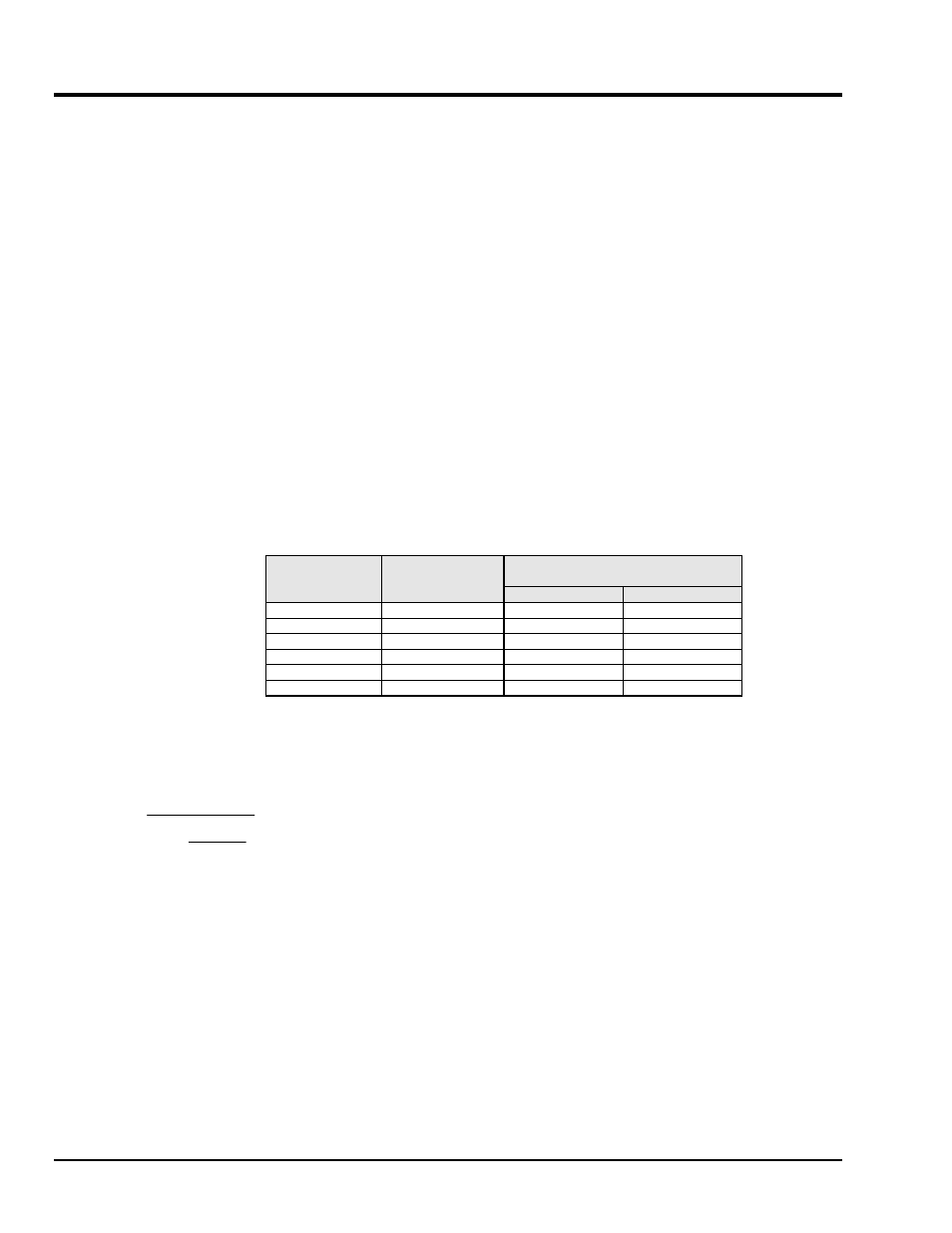
The maximum frequency that can be transmitted over a given length of cable is a function of both the cable
capacitance and the ratio of the maximum peak signal voltage to the current available from the constant
current source:
Frequency Response to 5% of
Maximum Output Signal Amplitude
Drive Current
(mA)
Cable Length
@30 pF/ft (Ft)
± 1 V
± 5 V
2
10
185 kHz
37 kHz
2
100
18.5 kHz
3.7 kHz
2
1000
1.85 kHz
370 Hz
4
10
550 kHz
110 kHz
4
100
55 kHz
11 kHz
4
1000
5.5 kHz
1.1 kHz
f
K
C
V
Icc Ib
=
−
2
π
Where:
f = Maximum frequency in Hz
K = 3.45 ×10
9
. K is the scale factor to convert Farads to picoFarads and Amperes to milliAmperes
and a factor to allow cable capacitance to charge to 95% of the final charge.
C = Cable capacitance in picoFarads
V = Maximum peak measured voltage from sensor in volts
Icc = Constant current from current source in mA
Ib = Current required to bias the internal electronics, typically 1 mA
WBK14 - Specifications
Specifications are provided in Chapter 11.