Onnection ……4-11, Connecting to chassis (ground) – Measurement Computing WavePort rev.3.0 User Manual
Page 39
WavePort User’s Manual
09-29-00
Hardware and Operation Reference 4-11
Connecting to CHASSIS (Ground)
WavePort includes a CHASSIS ground node. Though it never hurts to connect the WavePort CHASSIS to
a reliable ground, it is recommended that you do make this connection to ground when WavePort is …
• … being used in a vehicle.
• … being used in a static-prone environment.
• … experiencing Radio Frequency Interference (RFI) (see following note).
If WavePort experiences Radio Frequency Interference (RFI) you should:
(a) connect the WavePort CHASSIS to ground, and
(b) connect the cable-shields (of the channel inputs) to CHASSIS ground.
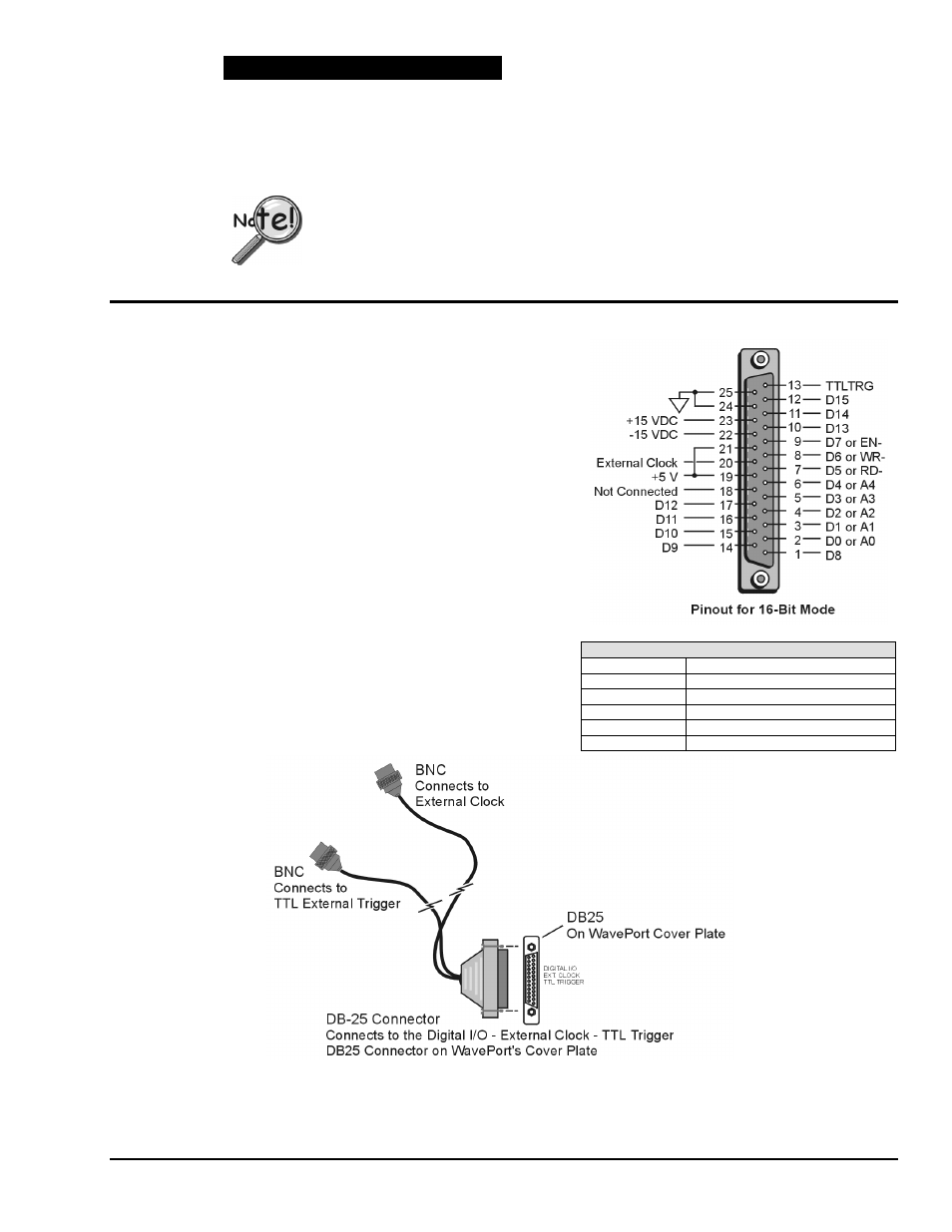
DB25F “Digital I/O, External Clock, TTL Trigger” Connection
Digital I/O Connections, WaveBook/516
D0 – D15
High Speed Digital I/O data lines
TTLTRG
TTL trigger input
External Clock
16 bit mode, read/write strobe
+5 VDC
250 mA maximum
+15,-15 VDC
50 mA maximum (each)
The following signals are present on WavePort’s DB25F
(25-pin, female connector) labeled “Digital I/O, External Clock, and
TTL Trigger.”
• 16 High-Speed Digital I/O Lines (D0 through D15)
• TTL Trigger Input (TTLTRG)
• +15 V (pin 23), -15 V (pin 22), 50 mA max. (each)
• two +5 V (pin 19 and pin 21), 250 mA max. (total)
• External Clock (pin 20)
• two Digital Grounds (pins 24 and 25)
To sample just 16 digital input signals, connect them directly to
the digital I/O data lines. D15 is the most significant bit, and D0
is the least.
The following figure depicts the DB25F connector (located on
WavePort’s cover plate) and the optional CA-178 cable. The
cable option is intended for External Clock and TTL External
Trigger applications. Both are discussed shortly.
Digital Grounds
Pins 24 and25
Optional Clock and External Trigger Cable (CA-178)