Measurement Computing WavePort rev.3.0 User Manual
Page 14
2-4 An Introduction to WavePort
09-29-00
WavePort User’s Manual
WavePort/PE8
WavePort/PE8 can measure up to eight channels of voltages within ±10V; and up to 8 channels of ICP
®
transducer excitation.
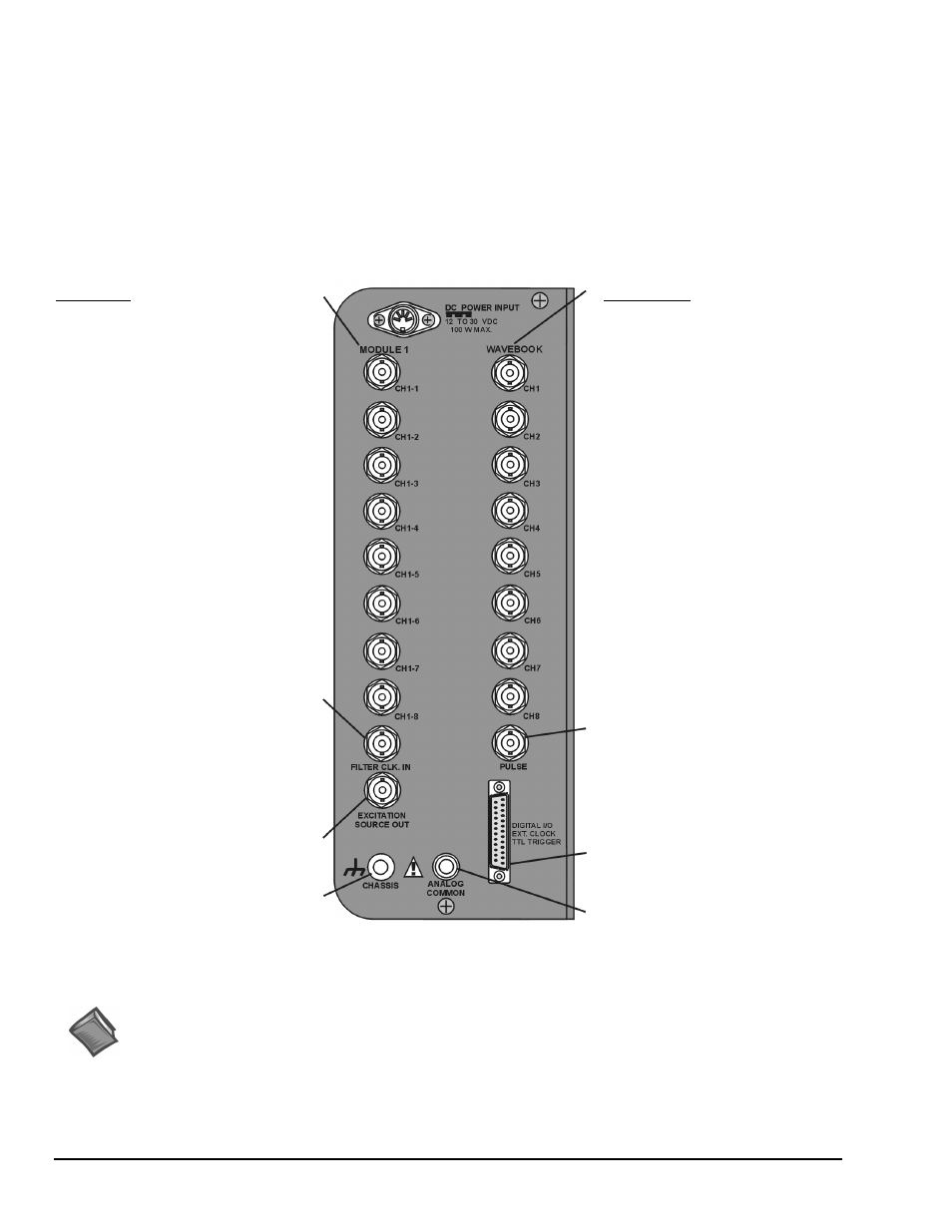
The unit receives its channel-input signals through two columns of eight BNC connectors (16 channel inputs total). The
columns are labeled MODULE 1 and WAVEBOOK. In addition to the channel-input BNCs, WAVEBOOK contains a BNC
for PULSE Trigger Input, and MODULE 1 include one BNCs for filter clock input (FILTER CLK. IN), and another BNC for
EXCITATION SOURCE OUT (see following figure).
The signal panel includes a DB25 connector for DIGITAL I/O, EXT CLOCK (external clock), and TTL TRIGGER.
Connection nodes for CHASSIS (ground) and ANALOG COMMON are also provided.
WaveBook
Analog Inputs
CH1 through CH8, Analog Inputs via
BNC Connectors.
• 16 bit resolution
• Software selectable for unipolar or
bipolar operation
• Unipolar Ranges
0 to +10V
0 to + 4V
0 to +2V
• Bipolar Ranges
±10V, ±5V, ±2V, ±1V
• Maximum Overvoltage: ±30 VDC
DC-Coupled Only,
Fully Differential
See Chapter 6, WaveView and
Chapter 10, Specifications for
additional information.
Module 1
Dynamic Signal Conditioning
CH1-1 through CH1-8
• Gain Ranges:
x1, 2, 5, 10, 20, 50, 100, and 200
• Input Ranges:
5V, 2.5V, 1V,
500 mV, 250 mV,
100 mV, 50 mV,
and 25 mV peak
AC-Coupled Only,
BNC shells are analog common.
See Chapter 6, WaveView and
Chapter 10, Specifications for
additional information.
Filter Clock In
Excitation Source Out
Chassis Ground
Pulse Trigger Input
• Input Signal Range: ±5V
• Input Characteristics: 75 Ω
• Input Protection: ±10V max.
• Minimum Pulse Width: 100 ns
• Maximum Pulse Width: 0.8 sec
• Latency: 300 ns
Digital I/O
External Clock
TTL Trigger
Analog Common
WavePort/PE8 Signal Panel
Reference Notes:
Additional information regarding WavePort signal connections appears elsewhere in this manual.
• Chapter 4, Hardware and Operation Reference, includes details regarding signal connections.
• Chapter 6, WaveView, includes information regarding channel configuration.
• Chapter 9 contains maintenance, intended environment, and transportation information.
• Chapter 10 provides device specifications.