Measurement Computing WavePort rev.3.0 User Manual
Page 13
WavePort User’s Manual
09-29-00
An Introduction to WavePort 2-3
WavePort/PE16
WavePort/PE16 can measure up to eight channels of voltages within ±10V; and up to 16 channels of ICP
®
transducer
excitation.
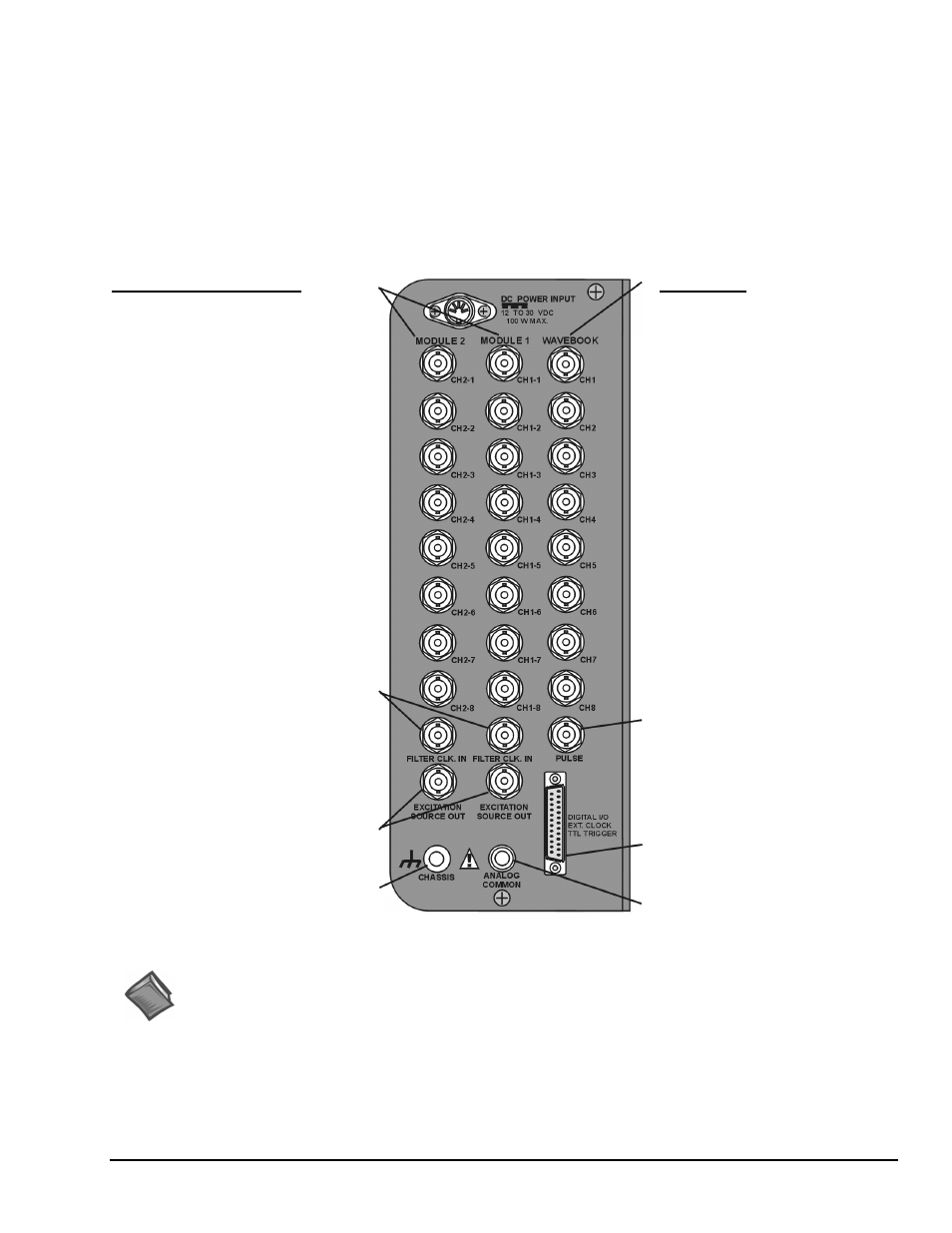
The unit receives its channel-input signals through three columns of eight BNC connectors (24 channel inputs total). The
columns are labeled MODULE 2, MODULE 1, and WAVEBOOK. In addition to the channel-input BNCs, WAVEBOOK
contains a BNC for PULSE Trigger Input, and the two MODULEs include BNCs for filter clock input (FILTER CLK. IN),
and EXCITATION SOURCE OUT (see following figure).
The signal panel includes a DB25 connector for DIGITAL I/O, EXT CLOCK (external clock), and TTL TRIGGER.
Connection nodes for CHASSIS (ground) and ANALOG COMMON are also provided. An illustration follows.
WaveBook
Analog Inputs
CH1 through CH8, Analog Inputs via
BNC Connectors.
• 16 bit resolution
• Software selectable for unipolar or
bipolar operation
• Unipolar Ranges
0 to +10V
0 to + 4V
0 to +2V
• Bipolar Ranges
±10V, ±5V, ±2V, ±1V
• Maximum Overvoltage: +/-30 VDC
DC-Coupled Only,
Fully Differential
See Chapter 6, WaveView and
Chapter 10, Specifications for additional
information.
Module 1 and Module 2
Dynamic Signal Conditioning
CH1-1 through CH1-8 and
CH2-1 through CH2-8, respectively
• Gain Ranges:
x1, 2, 5, 10, 20, 50, 100, and 200
• Input Ranges:
5V, 2.5V, 1V,
500 mV, 250 mV,
100 mV, 50 mV,
and 25 mV peak
AC-Coupled Only
BNC shells are analog common.
See Chapter 6, WaveView and
Chapter 10, Specifications for
additional information.
Filter Clock In
Excitation Source Out
Chassis Ground
Pulse Trigger Input
• Input Signal Range: ±5V
• Input Characteristics: 75 Ω
• Input Protection: ±10V max.
• Minimum Pulse Width: 100 ns
• Maximum Pulse Width: 0.8 sec
• Latency: 300 ns
Digital I/O
External Clock
TTL Trigger
Analog Common
WavePort/PE16 Signal Panel
Reference Notes:
Additional information regarding WavePort signal connections appears elsewhere in this manual.
• Chapter 4, Hardware and Operation Reference, includes details regarding signal connections.
• Chapter 6, WaveView, includes information regarding channel configuration.
• Chapter 9 contains maintenance, intended environment, and transportation information.
• Chapter 10 provides device specifications.