Measurement Computing WavePort rev.3.0 User Manual
Page 22
3-4 System Setup
06-14-00
WavePort User’s Manual
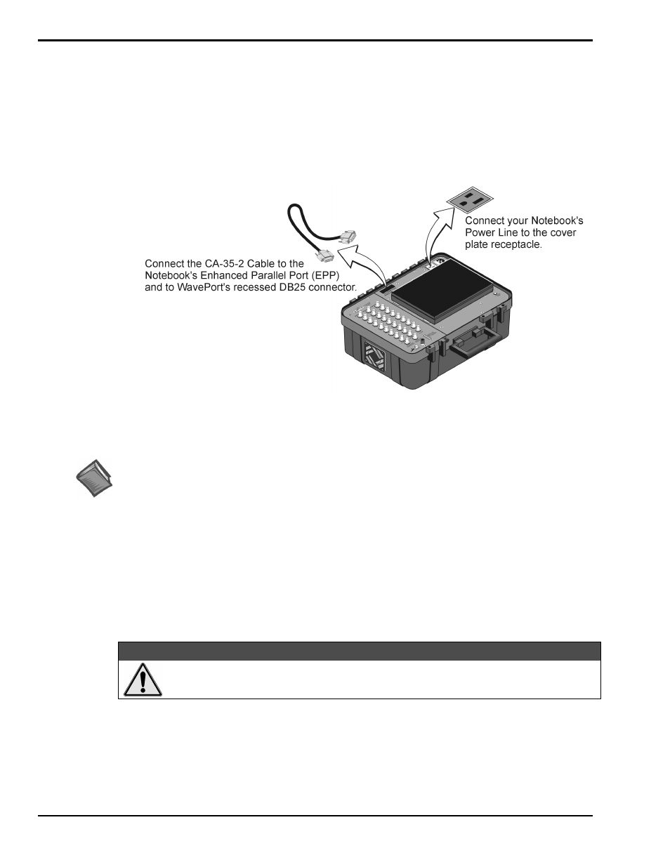
3. Connecting the Communication Cable and Notebook Power Cable
WavePort’s communication line connects to a host PC through a 25 pin (male connector) located in a
recess on WavePort’s cover plate. The connector is labeled “TO COMPUTER PARALLEL PORT.”
WavePort communicates with a Notebook through the PC’s enhanced parallel port (EPP). An
alternative is to use a WBK20A PCMCIA/EPP interface-card in conjunction with the Notebook’s
PC-Card port. This option is discussed in Appendix B.
Connecting the Notebook PC to WavePort
Reference Note:
An optional WBK20A PCMCIA/EPP interface-card can be used instead of the CA-35-2 cable.
WBK20A connects to the Notebook’s PC-Card port. This PC-Card option is discussed in Appendix B.
Connect the Notebook’s power line to the Notebook Power receptacle located on WavePort’s cover plate.
This receptacle is “live” whenever WavePort has AC line power connected to a live source. The position of
WavePort’s Module Power switch has no bearing on the Notebook Power receptacle.
The Notebook can be powered from the Notebook Power Receptacle [non-switched] as long as
LINE INPUT power is supplied to the WavePort (as discussed in the following section). Do not plug
anything into the Notebook Power Receptacle that exceeds a power rating of 50 Watts, as this could
overload the WavePort.
CAUTION
CAUTION
CAUTION
CAUTION
Do not plug anything into the Notebook Power Receptacle that exceeds a power rating of
50 Watts. Such action could result in overloading the WavePort and blowing a fuse.