Software setup, Wbk10a-based module specifications, S ……4-9 – Measurement Computing WavePort rev.3.0 User Manual
Page 37
WavePort User’s Manual
09-29-00
Hardware and Operation Reference 4-9
Signal Aspects, WavePort/V
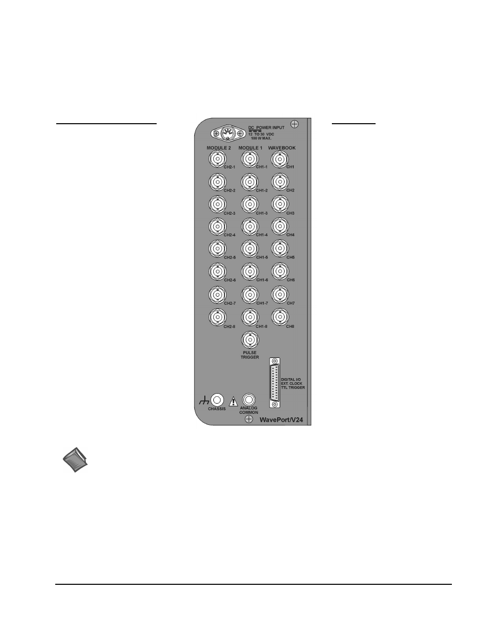
WavePort/V24 can measure up to 24 channels of voltages within ±10V. The V8 and V16 version WavePorts measure up to 8
and 16 channels, respectively. WavePort/V24 receives its channel-input signals through three columns of eight BNC
connectors (24 channel inputs total). The columns are labeled [from left to right] MODULE 2, MODULE 1, and
WAVEBOOK. In addition to the channel-input BNCs, WAVEBOOK contains a BNC for PULSE Trigger Input (see
following figure). Note that WavePortV8 and V16 BNC panels are illustrated in chapter 2.
The signal panel includes a DB25 connector for DIGITAL I/O, EXT CLOCK (external clock), and TTL TRIGGER.
Connection nodes for CHASSIS (ground) and ANALOG COMMON are also provided.
WaveBook
Analog Inputs
CH1 through CH8, Analog Inputs via
BNC Connectors.
• 16 bit resolution
• Software selectable for unipolar or
bipolar operation
• Unipolar Ranges
0 to +10V
0 to + 4V
0 to +2V
• Bipolar Ranges
±10V, ±5V, ±2V, ±1V
• Maximum Overvoltage: ±30 VDC
DC-Coupled Only,
Fully Differential
Module 1 and Module 2*
Analog Inputs
CH1-1 through CH1-8, and
CH2-1 through CH2-8, respectively.
• 16 bit resolution
• Software selectable for unipolar or
bipolar operation
• Unipolar Ranges
0 to +10V
0 to + 5V
0 t0 + 2V
0 to +1V
• Bipolar Ranges
±10V, ±5V, ±2V, ±1V, ±0.5V
• Maximum Overvoltage: ±30 VDC
DC-Coupled Only,
Fully Differential
See Chapter 6, WaveView and
Chapter 10, Specifications for
additional information that includes
ranges available with WBK11A,
WBK12A, and WBK13A factory-
installed options.
* WavePort/V16 does not include
Module 2. WavePort/V8 includes the
WaveBook and Pulse Trigger BNCs
(but no Module BNCs.
Chassis Ground
(See page 4-10)
Pulse Trigger Input (see page 4-13)
• Input Signal Range: ±5V
• Input Characteristics: 75 Ω
• Input Protection: ±10V max.
• Minimum Pulse Width: 100 ns
• Maximum Pulse Width: 0.8 sec
• Latency: 300 ns
Digital I/O (see page 4-11)
External Clock (see page 4-11, 15)
TTL Trigger (see page 4-11)
Analog Common (see page 4-10)
WavePort/V24 Signal Panel
Reference Notes: Additional information regarding WavePort signal connections appears elsewhere in this
manual. Chapter 6, WaveView, includes information regarding channel configuration.
Information regarding maintenance, intended environment, and transportation is included in chapter 9.
Specifications are provided in chapter 10.
Software Setup
You will need to set several parameters so WaveView can best meet your application requirements. For
software setup information, refer to the "Software Setup" section in Chapter 2, WaveBook Setup. For
detailed WaveView information, refer to Chapter 5, WaveView.
WBK10A-Based Module Specifications
Specifications are provided in chapter 10.