Measurement Computing WavePort 312P rev.1.0 User Manual
Page 70
9-2 Event Capture
PowerVista/312 User’s Manual
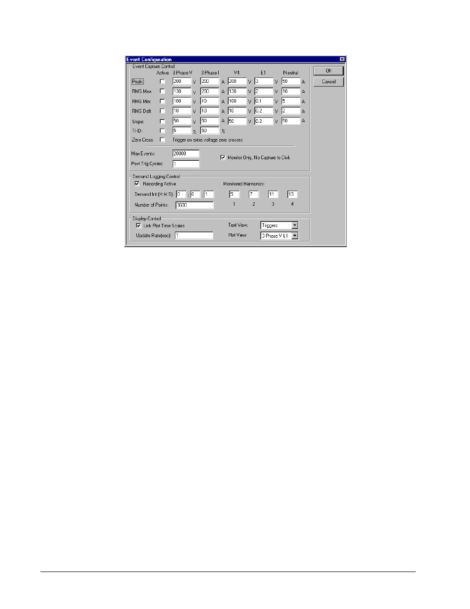
Figure 9-1. Event Capture Configuration Dialog.
Items in the Cycle-by-Cycle Configuration include:
• Peak Trigger: is an event trigger setting that is compared against the absolute signal peak value on
wave. When the peak value exceeds the Peak Trigger, event capture is initiated. This value is specified
in Volts or Amps as appropriate.
Note: This trigger will continuously capture data if it is set such that the Peak Trigger is continuously
exceeded. Care must be taken when setting this value as unnecessary and excessive collection of
data can occur.
• RMS Max Trigger: is an event trigger that starts event capture when it is transitioned. If the steady
state RMS voltage exceeds this value, it will only trigger an event as it moves through the trigger. This
value is specified in Volts or Amps as appropriate.
• RMS Min Trigger: is an event trigger that starts event capture when it is transitioned. If the steady
state RMS voltage is less than this value, it will only trigger an event as it moves through the trigger.
This value is specified in Volts or Amps as appropriate.
• RMS Delt Trigger: is an event trigger that is compared against the RMS voltage difference between
two successive cycles. When the difference exceeds the trigger value, event capture is initiated. This
value is specified in Volts or Amps as appropriate.
• Slope Trigger: is an event trigger that is compared against the worst case difference in a signal between
two successive data points. The method of supplying a voltage here for the trigger level is easier than
actual slope since users can think easily of a sample to sample voltage excursion. Actual slope (volts per
second) would have to be calculated before entry and users would have to be familiar with time between
samples. This value is specified in Volts or Amps as appropriate.