5 three phase delta – Measurement Computing WavePort 312P rev.1.0 User Manual
Page 40
4-6 Device Configuration
PowerVista/312 User’s Manual
4.1.5 Three Phase Delta
System Configuration PT Connection:
Delta
A three phase Delta connection is measured so that only a Two Wattmeter method is used to calculate power. It
is practically impossible to perform a single-line-to-ground measurement on a Delta system and determine a
correct three phase measurement. Only under ideal balanced conditions when parasitic and stray capacitance
perfectly center the artificial neutral point at the ground voltage can this be accomplished. As noted above, each
per phase power value will be determined as the Two Wattmeter Method total three phase power value divided
by three.
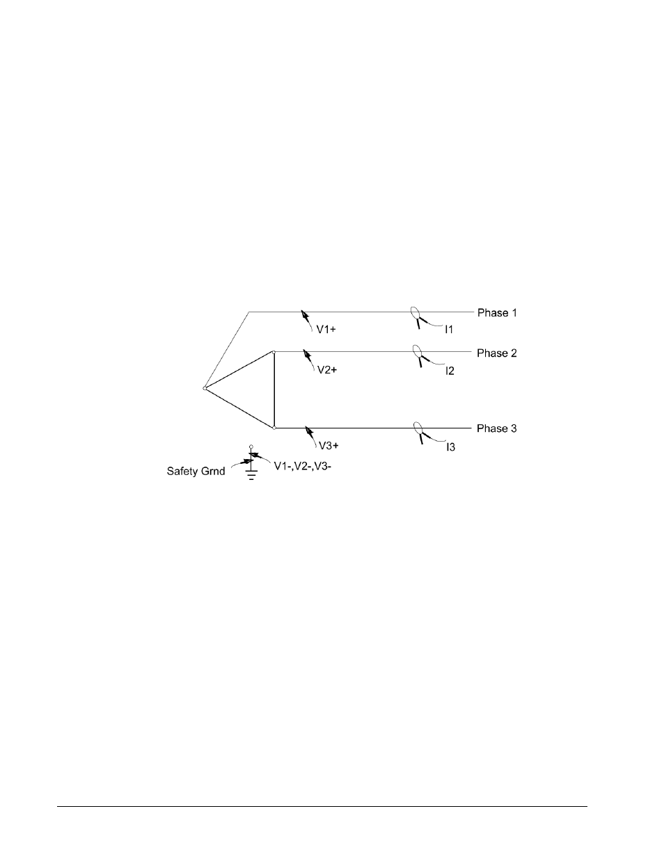
Notice that connections
in Figure 4-5
show each V- lead connected to system ground. To keep users from
potentially dangerous connections on the hardware, EasyPower Measure performs all differential calculations
internally in software. Thus, no line to line connections are needed. If line-to-line connections were used, and
the user employed jumpers at the sheathed banana inputs to the hardware to limit leads going to the point of
connection to three, there would be a potential of causing a line-to-line fault with the jumpers. We reduce the
chance of an accidental short during lead connections greatly using the method described here.
Figure 4-5. Connection Arrangement for a Delta System.
Note that even though EasyPower Measure performs differential calculations internally, all inputs to the
hardware are truly differential. If the user desires to connect up leads line-to-line, this can be done. Also,
differential inputs allow the user to simultaneously monitor (via channel V4) the DC bus voltage on a drive
system for example.Safety ground and the V1, V2 and V3 negative inputs should be connected to the nearest
bonafied system ground point.