Chapter 4 - device configuration, Signal connections, 4 device configuration – Measurement Computing WavePort 312P rev.1.0 User Manual
Page 35: 1 signal connections, Warning
PowerVista/312 User’s Manual
Device Configuration 4-1
4 Device Configuration
4.1 Signal
Connections
WARNING !
ELECTRIC SHOCK HAZARD! Use proper electrical safety precautions when operating
this equipment. Ensure the Safety Ground is connected firmly to a good earth ground. The
safety ground connection must always be made FIRST (before leads and clamp-ons are
attached) and must always be the LAST connection removed (after all leads and clamp-ons
are removed).
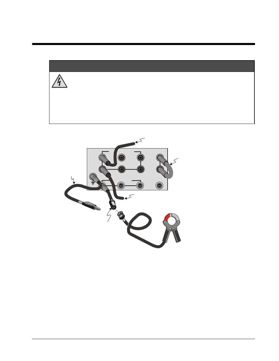
Place protective shorts in V1, V2, V3, and V4 when the applicable input jack is not in use.
Use only those connectors that are approved for this device. Failure to observe safe
electrical practices could result in death or serious injury from electric shock.
V2
V3
V4
I1
I2
I3 E1
3 Phase I (5V Peak)
3 Phase V (1250V Peak)
(1250V Peak)
(5V Peak)
Extra
GND
Safety
Protective Short. Place short in
voltage input connectors that
are not receiving input.
(For clarity of figure, the short is
shown only in V4)
1250V Peak Differential Input using
Sheathed Banana Safety Connector
(shown for red connector V1)
1250V Peak Differential Input using
Sheathed Banana Safety Connector
(shown for black connector V1)
Note: Items are not drawn to scale.
4-Plug MiniDIN/Alligator Clip
Cable (Green)
5-Plug MiniDIN/BNC
Cable (for 3 phase current,
5V peak measurements)
Clamp-on ammeter for 3 phase current.
Equipped with BNC cable for connecting
directly to BNC end of 5-Plug MiniDIN/BNC
cable.
Connect to earth ground,
See above Warning!
Figure 4-1. Signal Connection Panel and Connection Types
Safety GND – Use the green MiniDIN/Alligator Clip Connection to connect PowerVista/312 firmly to a good
earth ground. As noted in the previous Warning, the safety ground must always be the FIRST connection
made and must always be the LAST connection removed.
3 Phase V (1250V Peak Differential Input) – For V1, V2, V3, and V4. Use Sheathed Banana Safety
Connectors. Do not attempt to measure voltage differentials that exceed the specified limit of 1250V peak.
Place “C” shaped protective shorts in each voltage input jack that will not be receiving an input line.
Protective Short - For V1, V2, V3, and V4. Use Protective Shorts in each voltage input jack that will not be
receiving an input line.
3 Phase Current (5V Peak) – For I1, I2, I3, and E1. Connect the ammeter’s MiniBNC cable to the
MiniDIN/BNC cable, then connect to I1, I2, I3, or E4 as applicable.