Redundancy configuration, Mounting kit, Figure a-9. redundancy configuration – Comtech EF Data XSAT-7080 User Manual
Page 93: A.5.1 m
XSAT7080 X-Band Transceiver
Revision 0
5-25W Installation
MN/XSAT7080.IOM
A–11
A.5
R
EDUNDANCY
C
ONFIGURATION
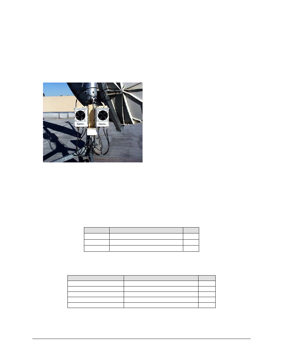
Figure A-9. Redundancy
Configuration
A.5.1 M
OUNTING
K
IT
The following tables reflect the contents of the mounting kits.
Table A-2. 1:1 Mounting Kit Assembly, AS/0596
Part No.
Nomenclature
QTY
*AS/0414 Kit, Redundancy, Pole Mount
2
AS/0489 Assy, 1:1 25W XSAT
1
*AS/0608 Assy, Bracket Mount 25W XSAT
2
* - Refer to single-thread configuration
Table A-3. Assembly, 1:1 25W XSAT, AS/0510
Part No.
Nomenclature
QTY
AS/9751-1
Kit, Mounting LNA Switch
1
AS/0440
Kit, Cable, 1:1 X-Band
1
PL/9512
Kit, Waveguide
1
AS/0490
Assy, Remote Switch Cast Box
1
AS/0503
Assembly, TX/Remote Switch
1
See also other documents in the category Comtech EF Data Equipment:
- CDD-880 (124 pages)
- CDM-800 (130 pages)
- ODMR-840 (184 pages)
- CDM-750 (302 pages)
- CDM-840 (244 pages)
- SLM-5650A (420 pages)
- CTOG-250 (236 pages)
- CDM-700 (256 pages)
- CDM-760 (416 pages)
- CDM-710G (246 pages)
- CDM-600/600L (278 pages)
- CDMR-570L (512 pages)
- CDM-625 (684 pages)
- CDM-625A (756 pages)
- CDD-564A (240 pages)
- CDD-564L (254 pages)
- CLO-10 (134 pages)
- MCED-100 (96 pages)
- CDMR-570AL (618 pages)
- CDM-600 LDPC (2 pages)
- BUC Power Supply Ground Cable (2 pages)
- MPP70 Hardware Kit for CDM-570L (4 pages)
- MPP50 Hardware Kit for CDM-570L (4 pages)
- CDM-625 DC-AC Conversion (4 pages)
- CDM-625 DC-AC Conversion with IP Packet Processor (4 pages)
- DMDVR20 LBST Rev 1.1 (117 pages)
- DMD2050E (212 pages)
- DMD-2050 (342 pages)
- DMD1050 (188 pages)
- OM20 (220 pages)
- QAM256 (87 pages)
- DD240XR Rev Е (121 pages)
- MM200 ASI Field (5 pages)
- DM240-DVB (196 pages)
- MM200 (192 pages)
- CRS-150 (78 pages)
- CRS-280L (64 pages)
- CRS-170A (172 pages)
- CRS-180 (136 pages)
- SMS-301 (124 pages)
- CiM-25/8000 (186 pages)
- CiM-25 (26 pages)
- CRS-500 (218 pages)
- CRS-311 (196 pages)
- CIC-20 LVDS to HSSI (26 pages)