Comtech EF Data XSAT-7080 User Manual
Page 101
XSAT7080 X-Band Transceiver
Revision 0
5-25W Installation
MN/XSAT7080.IOM
A–19
A.5.3 C
ONNECT
C
ABLING TO THE
R
EMOTE
S
WITCH
B
OX
, AS/0490
USING
AS/0440 C
ABLE
K
IT
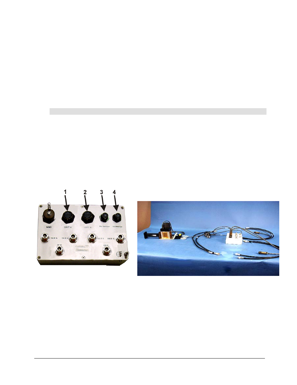
Note: Refer to Figure A-18a for assembled view, refer to Figure A-21for LNA port
locations, and refer to Figure A-12 for Cable kit.
Step
Procedure
1
Connect one end of the Control cable, (4, Figure A-12) to UNIT A
(1, Figure A-17) connector.
2
Connect one end of the Control cable, (5) to UNIT B (2, Figure A-17)
connector.
3
Connect one end of Cable (2) to RX SWITCH (3 , Figure A-17) connector.
4
Connect one end of Cable (3, figure A-13) to TX SWITCH connector (4 ,
Figure A-17). Set box aside for later installation.
5
The four RF cables, (1, Figure A-12) are used to connect the IF ports on the
switch controller to the units.
Figure A-17. Remote Switch Cast Box
Figure A-18a. Switch Box with Cables
- CDD-880 (124 pages)
- CDM-800 (130 pages)
- ODMR-840 (184 pages)
- CDM-750 (302 pages)
- CDM-840 (244 pages)
- SLM-5650A (420 pages)
- CTOG-250 (236 pages)
- CDM-700 (256 pages)
- CDM-760 (416 pages)
- CDM-710G (246 pages)
- CDM-600/600L (278 pages)
- CDMR-570L (512 pages)
- CDM-625 (684 pages)
- CDM-625A (756 pages)
- CDD-564A (240 pages)
- CDD-564L (254 pages)
- CLO-10 (134 pages)
- MCED-100 (96 pages)
- CDMR-570AL (618 pages)
- CDM-600 LDPC (2 pages)
- BUC Power Supply Ground Cable (2 pages)
- MPP70 Hardware Kit for CDM-570L (4 pages)
- MPP50 Hardware Kit for CDM-570L (4 pages)
- CDM-625 DC-AC Conversion (4 pages)
- CDM-625 DC-AC Conversion with IP Packet Processor (4 pages)
- DMDVR20 LBST Rev 1.1 (117 pages)
- DMD2050E (212 pages)
- DMD-2050 (342 pages)
- DMD1050 (188 pages)
- OM20 (220 pages)
- QAM256 (87 pages)
- DD240XR Rev Е (121 pages)
- MM200 ASI Field (5 pages)
- DM240-DVB (196 pages)
- MM200 (192 pages)
- CRS-150 (78 pages)
- CRS-280L (64 pages)
- CRS-170A (172 pages)
- CRS-180 (136 pages)
- SMS-301 (124 pages)
- CiM-25/8000 (186 pages)
- CiM-25 (26 pages)
- CRS-500 (218 pages)
- CRS-311 (196 pages)
- CIC-20 LVDS to HSSI (26 pages)