Redundant system, Chapter 5. redundant system, Edundant – Comtech EF Data XSAT-7080 User Manual
Page 57: Ystem
5-1
Chapter 5. REDUNDANT SYSTEM
Note: At this time, this section reflects the XSAT-70809 5 to 25 WATT and the XSAT-7080
100-WATT units only.
The XSAT-7080, is capable of operating in both stand-alone and redundant configurations. The
XSAT fully redundant system provides automatic detection, switching, and status for both its
configuration and health. The system is designed such that stand-alone operation is a functional
sub-set of the fully redundant XSAT system. This provides the user with transparent
functionality regardless of the mode or complexity the system has been setup to operate in.
IMPORTANT
Due to the parallel nature of the M&C interface, only RS-485 and RS-422
communications are supported through this device.
5.1 R
EDUNDANT
S
YSTEM
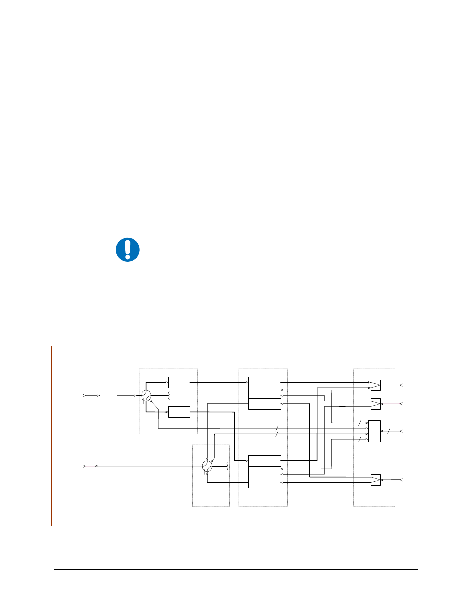
Figure 5-1 provides a block diagram for a typical XSAT redundant system.
Figure 5-1. Typical XSAT Redundant System, without IF Transfer Switches
DOWN
CONV
RF IN
CSAT
LNA 2
M&C
RF OUT
IF IN
UP
CONV
EXT REF
DOWN
CONV
RF IN
IF OUT
CSAT
M&C
IF IN
UP
CONV
Com
EXT REF
CONT
UNIT
Com
IF OUT
19
70 MHz
OUTPUT
70 MHz
INTPUT
10 MHz
INPU
OPTIONAL
RF
FROM
FEED
RF
TO
COM
TRANSCEIVER
6
RF OUT
WG
LNA WG SWITCH
CPR13
7
RSU-5060
Tx WG SWITCH
Tx
FILTER
OPTIONAL
OPTIONAL
LNA 1
CPR22
9 WG
19
19
6
CPR13
7
CPR13
7
A1
A2
W1
W1
C1
C1
CPR22
9
CPR22
9
W3
W3
A3
A4
A4
W2
CPR22
9
T1
T2
C4
C4
C4
C4
C5
C5
C2
C3
FEED