Figure 5-2 for examples, And figure 5-2), And figure 5-2 – Dot Hill Systems II 200 FC User Manual
Page 90
5-8 SANnet II 200 FC, SATA, and SATA SE Array Installation, Operation, and Service Manual • March 2005
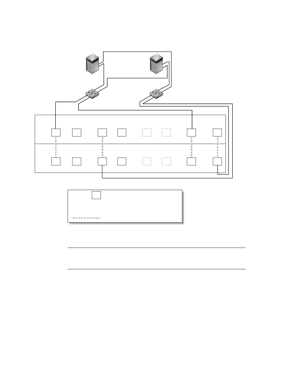
Figure 5-2 A Point-to-Point Configuration With a Dual-Controller SANnet II 200 SATA Array and
Two Switches
Note –
These illustrations show the default controller locations; however, the primary
controller and secondary controller locations can occur in either slot and depend on
controller resets and controller replacement operations.
Table 5-1 summarizes the primary and secondary host IDs assigned to logical drives 0
and 1, as shown in Figure 5-1 and Figure 5-2.
: Host port on channel number N
PID 40 / PID43 : Host IDs on primary controller
SID 45 / SID46 : Host IDs on secondary controller
N/A : Not applicable (no ID on that controller)
: Port bypass circuit
N/A
Switch 0
Server 0
Switch 1
Server 1
N
PID 40
PID 43
N/A
SID 45
N/A
N/A
SID 46
Map LG0 to PIDs 40 and 43
Map LG1 to SIDs 45 and 46
A
A
C
C
H
H
G
G