12 sii eeprom interface (i²c), 1 signals, 2 eeprom emulation – BECKHOFF EtherCAT IP Core for Xilinx FPGAs v3.00k User Manual
Page 139: 3 timing specifications, Sii eeprom interface (i²c), Signals, Eeprom emulation, Timing specifications, Table 66: i²c eeprom signals, Table 67: eeprom timing characteristics ip core
SII EEPROM Interface (I²C)
Slave Controller
– IP Core for Xilinx FPGAs
III-127
12 SII EEPROM Interface (I²C)
For details about the ESC SII EEPROM Interface refer to Section I. The SII EEPROM Interface is
intended to be a point-to-point interface between IP Core and I²C EEPROM. If other I²C masters are
required to access the I²C bus, the IP Core must be held in reset state (e.g. for in-circuit-programming
of the EEPROM).
12.1 Signals
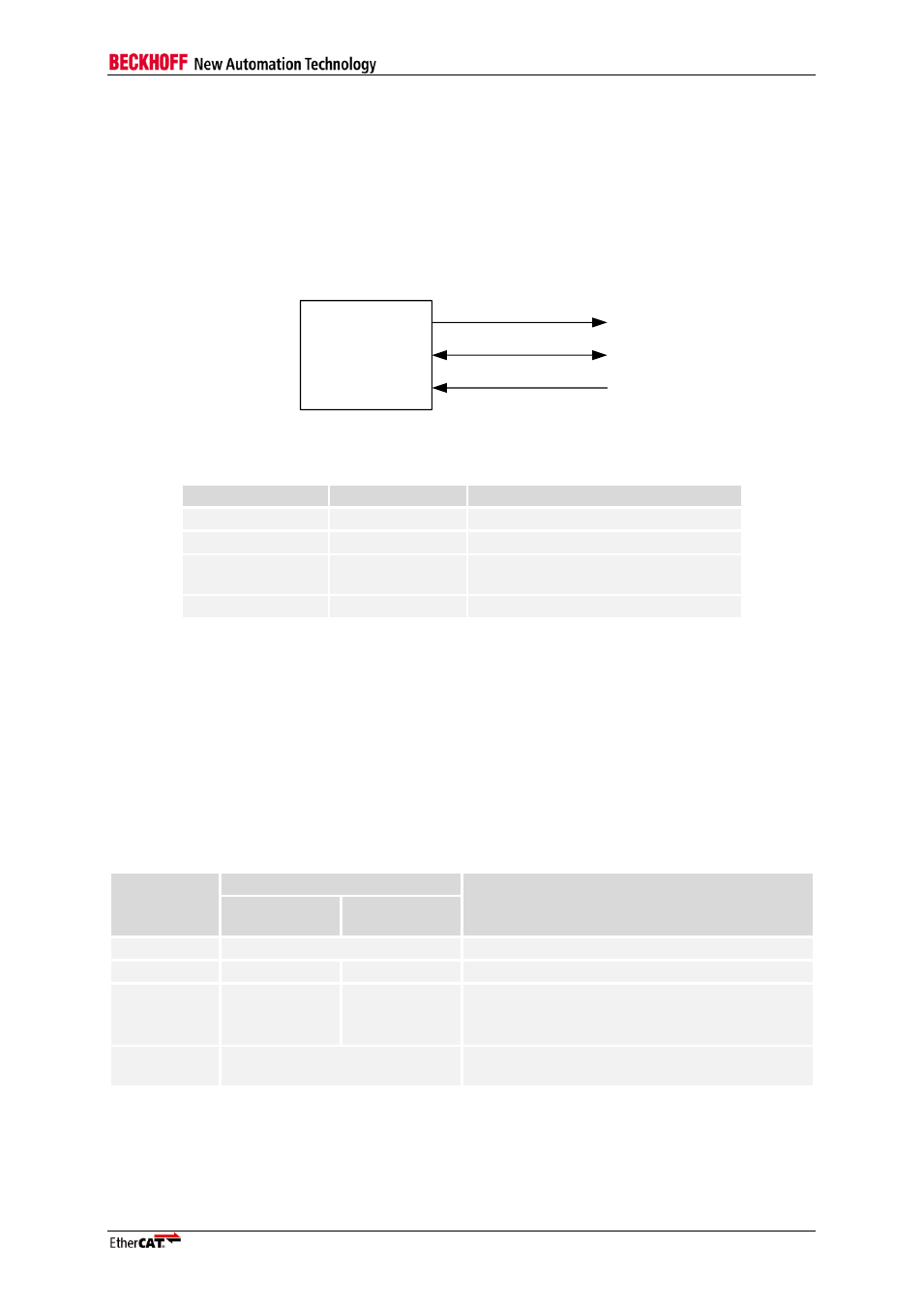
The EEPROM interface of the IP Core has the following signals:
EtherCAT
device
PROM_DATA
PROM_CLK
PROM_SIZE
Figure 66: I²C EEPROM signals
Table 66: I²C EEPROM signals
Signal
Direction
Description
PROM_CLK
OUT
I²C clock (alias EEPROM_CLK)
PROM_DATA
BIDIR
I²C data (alias EEPROM_DATA)
PROM_SIZE
IN
EEPROM size configuration (alias
EEPROM_SIZE)
PROM_LOADED
OUT
EEPROM is loaded (act. high)
Both EEPROM_CLK and EEPROM_DATA must have a pull-up resistor (4.7 k
Ω recommended for
ESCs), either integrated into the ESC or externally.
PROM_LOADED should have a pull-down resistor either integrated into the ESC or externally to have
a valid signal while the FPGA is configured.
12.2 EEPROM Emulation
EEPROM_SIZE has to be 0 for EEPROM emulation (EEPROM emulation with EEPROM_SIZE=1 is
for testing only: all commands are acknowledged automatically).
12.3 Timing specifications
Table 67: EEPROM timing characteristics IP Core
Parameter
Typical
Comment
Up to 16 KBit
32 KBit-
4 MBit
t
Clk
~ 6.72 µs
EEPROM clock period (f
Clk
≈ 150 kHz)
t
Write
~ 250 us
~ 310 µs
Write access time (without errors)
t
Read
a) ~ 440 µs
b) ~ 1.16 ms
a) ~ 500 µs
b) ~ 1.22 ms
Read access time (without errors):
a) 2 words
b) configuration (8 Words)
t
Delay
~ 60 µs
Time until configuration loading begins after
Reset is gone