Generator voltage sensing inputs, Phase b line current sensing input, Raise and lower contact inputs – Basler Electric BE2000E User Manual
Page 32: Var/power factor control contact input, Parallel generator compensation, Analog (auxiliary) adjust, Power supply inputs, Chassis ground
24
9287500995 Rev B
Generator Voltage Sensing Inputs
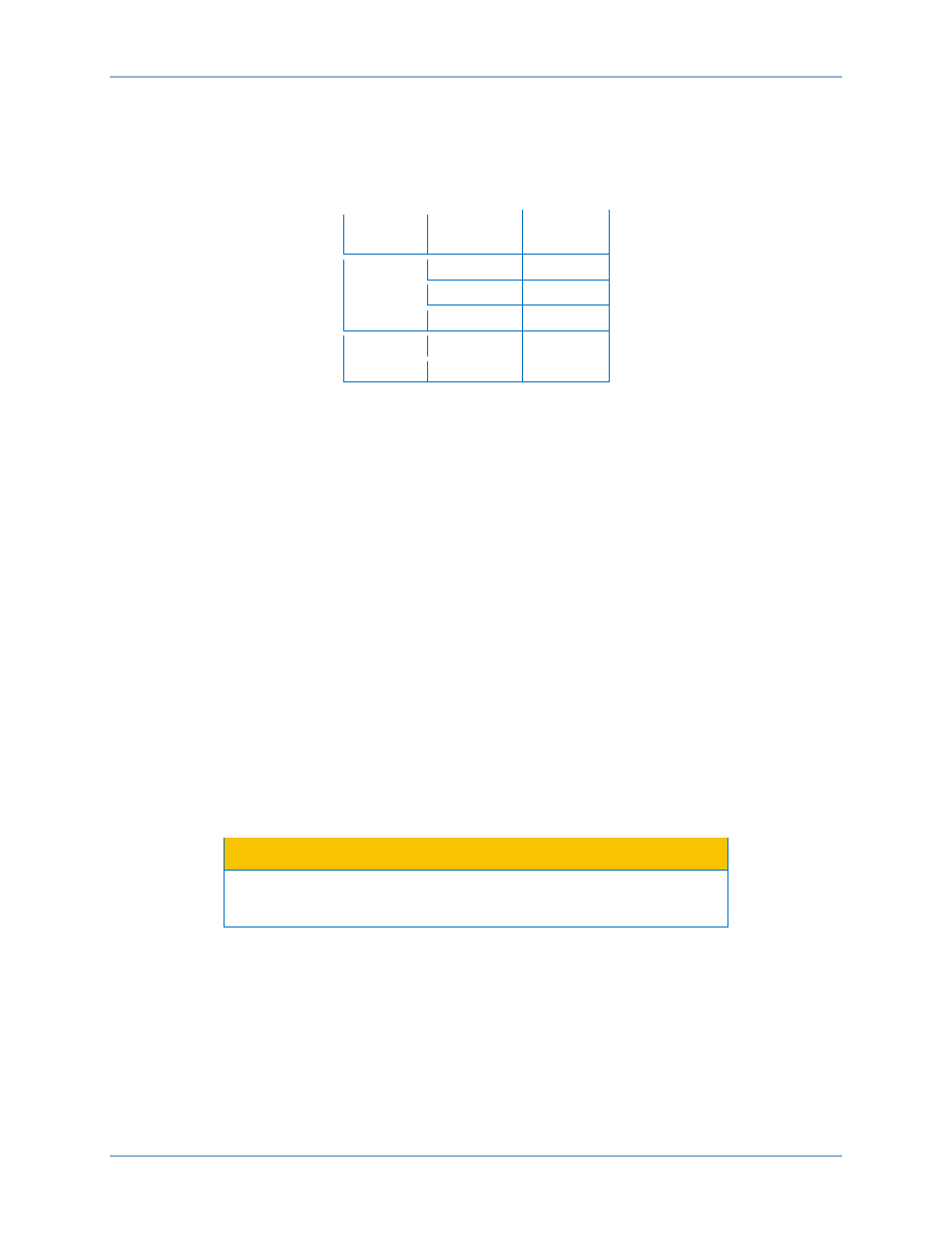
The generator voltage sensing terminals are labeled E1, E2, and E3. A single-phase sensing connection
is obtained by connecting the C-phase sensing input to terminals E2 and E3. Table 16 lists the terminal
assignments for three-phase and single-phase generator voltage sensing.
Table 16. Generator Voltage Sensing Terminals
Sensing
Generator
Phase
Terminal
3-Phase
A
E1
B
E2
C
E3
1-Phase
A
E1
C
E2, E3
Phase B Line Current Sensing Input
Generator line current is stepped down through a user-supplied current transformer (CT). Secondary
current from that transformer is applied to terminals labeled CT1 and CT2.
Raise and Lower Contact Inputs
Remote setpoint adjustment may be accomplished by connecting a single-pole, double-throw (SPDT),
spring return, center-off switch to the terminals labeled 6U, 7, and 6D. To connect this switch, the center
pole, or common terminal, must be connected to terminal 7. The other two terminals are connected to
terminals 6U and 6D. This remote adjust switch may be mounted up to 150 feet (45 meters) away from
the BE2000E when using twisted, shielded cable.
Var/Power Factor Control Contact Input
A customer supplied enable/disable contact for this function connects to the terminals labeled 52J and
52K. This function is disabled by a closed contact.
Parallel Generator Compensation
A customer supplied enable/disable contact for this function connects to the terminals labeled 52L and
52M. This function is disabled by a closed contact.
Analog (Auxiliary) Adjust
Caution
If the dc voltage is removed from the Analog (Auxiliary) Input, the
operating setpoint will return to the original value.
This input allows adjustment of the BE2000E regulation setpoint by the application of a positive or
negative dc voltage across terminals A and B. Voltage up to +3 Vdc may be applied at this input. The
circuit induces a 1,000-ohm burden on the dc source. The application of a +3 Vdc signal corresponds to a
+30 percent change in setpoint.
Power Supply Inputs
Power input terminals are labeled 3 and 4.
Chassis Ground
The chassis ground terminal is labeled GND.
Installation
BE2000E