7 vmebus p2 connector (ipmc mode), Table 5-14, Vme p2 connector pinouts with ipmc712 – Artesyn MVME6100 Single Board Computer Installation and Use (June 2014) User Manual
Page 97: Vmebus p2 connector (ipmc mode), Pin assignments
Pin Assignments
MVME6100 Single Board Computer Installation and Use (6806800D58H)
97
The default configuration for P2, C27-C30 are connected to PMC0_IO (53,55,57,59).
5.2.7
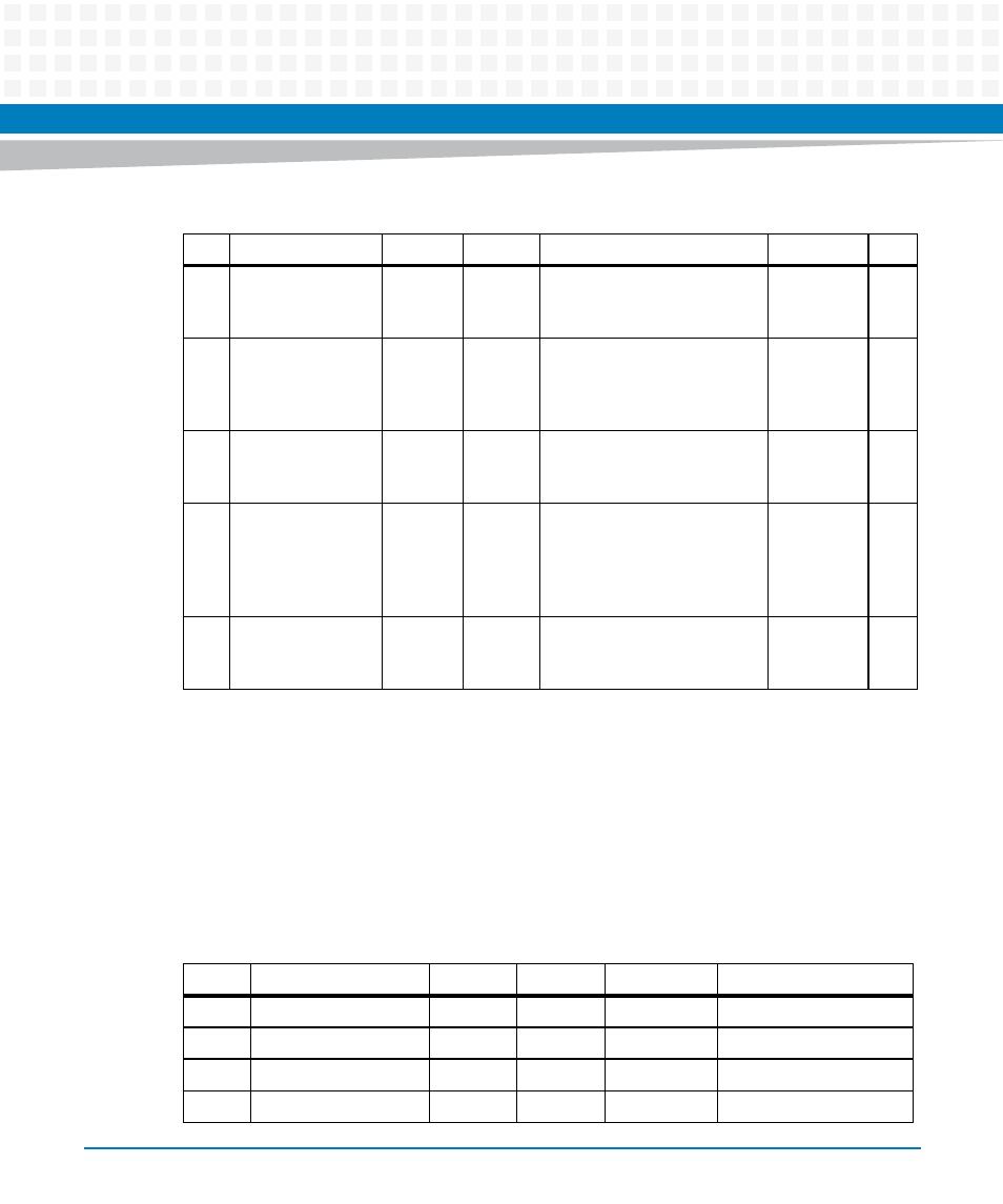
VMEbus P2 Connector (IPMC Mode)
The VME P2 connector is an 160-pin DIN. Row B of the P2 connector provides power to the
MVME6100 and to the upper eight VMEbus address lines and additional 16 VMEbus data lines.
The pin assignments for the P2 connector are as follows:
28
GND
PMC0_5
6 (J14-
56)
VD29
PMC0_55
(J14-55)/RXB
PMC1_42
(J24-42)
28
29
PMC1_44 (J30 D9-
C9) or
P2_IO_GLAN1_M
DIO_3- (J30 B9-C9)
PMC0_5
8 (J14-
58)
VD30
PMC0_57
(J14-57)/RTSB
PMC1_43
(J24-43)
29
30
GND
PMC0_6
0
(J14-60)
VD31
PMC0_59
(J14-59)/CTSB
PMC1_45
(J24-45)
30
31
PMC1_46 (J30
D10-C10) or
P2_IO_GLAN1_M
DIO_3+ (J30 B10-
C10)
PMC0_6
2 (J14-
62)
GND
PMC0_61
(J14-61)
GND
31
32
GND
PMC0_6
4 (J14-
64)
+5V
PMC0_63
(J14-63)
VPC
32
Table 5-13 VMEbus P2 Connector Pin Assignments (PMC Mode) (continued)
ROW Z
ROW A
ROW B
ROW C
ROW D
Table 5-14 VME P2 Connector Pinouts with IPMC712
Pin
Row Z
Row A
Row B
Row C
Row D
1
PMC2_2
DB0#
+5V
RD-
PMC2_1 (J24-1)
2
GND
DB1#
GND
RD+
PMC2_3 (J24-3)
3
PMC2_5
DB2#
N/C
TD-
PMC2_4 (J24-4)
4
GND
DB3#
VA24
TD+
PMC2_6 (J24-6)
- ARTM-9405 16x10GbE Installation and Use Guide (May 2014) (64 pages)
- ATCA 7370 / ATCA 7370-S Installation and Use (January 2015) (256 pages)
- ATCA 7370 / ATCA 7370-S Installation and Use (September 2014) (254 pages)
- ARTM-831X Installation and Use (June 2014) (346 pages)
- ATCA-7350 - Integrating with Workbench User Guide (September 2014) (34 pages)
- ATCA-7350 Installation and Use (September 2014) (208 pages)
- ATCA-7365-CE Installation and Use (May 2014) (306 pages)
- ATCA-7365-CE Installation and Use (Jan 2015) (300 pages)
- ATCA-7365-CE Installation and Use (May 2014) (294 pages)
- ATCA-7368 Installation and Use (June 2014) (222 pages)
- ATCA-7475 Installation and Use (October 2014) (284 pages)
- ATCA-7480 Installation and Use (April 2015) (330 pages)
- ATCA-8330 Installation and Use (April 2015) (236 pages)
- ATCA-8320 Installation and Use (May 2014) (456 pages)
- ATCA-9305 User's Manual (May 2014) (270 pages)
- ATCA-9405 Installation and Use (October 2014) (168 pages)
- ATCA-F120 Installation and Use (August 2014) (122 pages)
- ATCA-F140 Installation and Use (September 2014) (138 pages)
- ATCA-MF106 Installation and Use (September 2014) (86 pages)
- Centellis-4440/AXP1440 Installation and Use (September 2014) (208 pages)
- Centellis 4410 (AXP-1410) Installation and Use (July 2014) (202 pages)
- Centellis 2100 Release 3.0 Installation and Use (March 2015) (192 pages)
- Centellis 2100 Release 3.0 Installation and Use (March 2015) (176 pages)
- Centellis 2000 User Card-10GE Installation and Use (May 2014) (54 pages)
- Centellis 2000 User Card-10GE with Telco Alarm Installation and Use (May 2014) (60 pages)
- COMX-CAR-210 Installation and Use (August 2014) (76 pages)
- COMX-P1022 Installation and Use (July 2014) (84 pages)
- COMX-P2020 Installation and Use (February 2015) (100 pages)
- COMX-CORE Series Installation and Use (August 2014) (128 pages)
- COMX-P2020 Installation and Use (July 2014) (100 pages)
- COMX-P4080-2G-ENP2 Installation and Use (August 2014) (70 pages)
- COMX-P4080 Installation and Use (August 2014) (126 pages)
- COMX-P40x0 ENP2 Installation and Use (August 2014) (130 pages)
- COMX-P40x0 ENP2 Installation and Use (January 2015) (140 pages)
- iVPX7225 RTM Installation and Use (April 2015) (56 pages)
- MITX-430/MITX-440-DVI-2E Installation and Use (August 2014) (118 pages)
- CPCI-6200 Installation and Use (May 2015) (234 pages)
- SCP-MITX-CORE-820-SM Installation and Use (August 2014) (132 pages)
- iVPX7225 Installation and Use (April 2015) (168 pages)
- MVME2502 Installation and Use (August 2014) (150 pages)
- MVME2502 Installation and Use (December 2014) (166 pages)
- MVME2500 VxWorks 6.8 AMP User Guide (August 2014) (40 pages)
- MVME2500 VxWorks 6.8 User Guide (April 2014) (44 pages)
- MVME3100 Single Board Computer Installation and Use (June 2014) (156 pages)
- MVME4100 Single Board Computer Installation and Use (June 2014) (136 pages)