4 com2 header (j29), Table 5-18, Pmc/ipmc configuration jumper block – Artesyn MVME6100 Single Board Computer Installation and Use (June 2014) User Manual
Page 102: Table 5-19, Com2 header (j29), Pin assignments
Pin Assignments
MVME6100 Single Board Computer Installation and Use (6806800D58H)
102
5.3.3
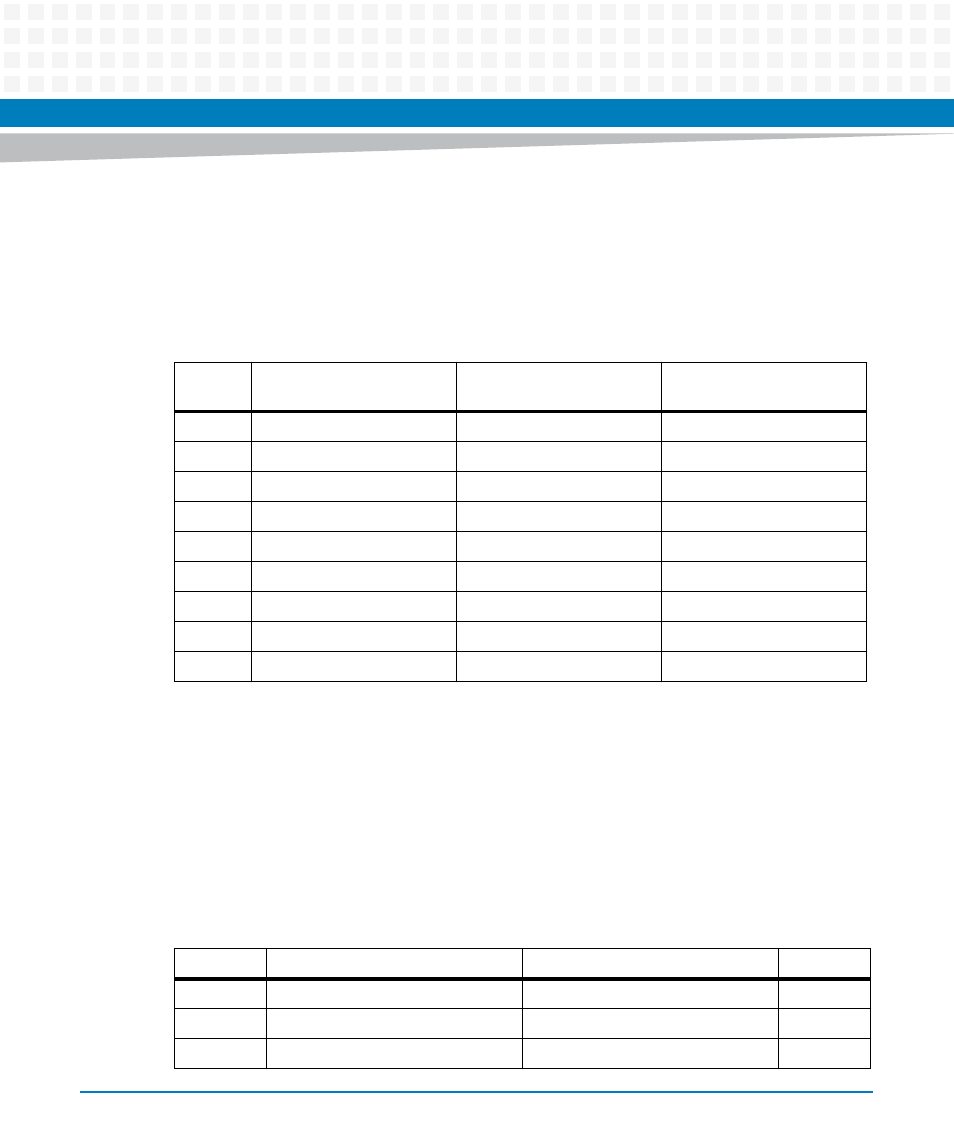
PMC/IPMC Selection Headers (J10, J15 – J18, J25 – J28)
Nine 3-pin 2 mm planar headers allow for PMC/IPMC I/O selection. These nine headers can also
be combined into one single header block where a block shunt can be used as a jumper. The pin
assignments for these connectors are as follows:
A jumper installed across pins 2 and 3 on all nine headers selects PMC1 I/O for IPMC mode.
5.3.4
COM2 Header (J29)
A 10-pin 0.100" planar header provides the interface to a second asynchronous serial debug
port. COM2 only goes to the on-board header as the default configuration. The pin
assignments for this header are as follows:
Table 5-18 PMC/IPMC Configuration Jumper Block
Pin/Row 1
(PMC I/O)
Pin/Row 2
(P2 Pins)
Pin/Row 3
(IPMC Pins)
J28
PMC1_IO(2)
P2_PMC1_IO(2)
IPMC DB8_L
J16
PMC1_IO(5)
P2_PMC1_IO(5)
IPMC DB9_L
J18
PMC1_IO(8)
P2_PMC1_IO(8)
IPMC DB10_L
J25
PMC1_IO(11)
P2_PMC1_IO(11)
IPMC DB11_L
J27
PMC1_IO(14)
P2_PMC1_IO(14)
IPMC DB12_L
J26
PMC1_IO(17)
P2_PMC1_IO(17)
IPMC DB13_L
J17
PMC1_IO(20)
P2_PMC1_IO(20)
IPMC DB14_L
J10
PMC1_IO(23)
P2_PMC1_IO(23)
IPMC DB15_L
J15
PMC1_IO(26)
P2_PMC1_IO(26)
IPMC DBP1_L
Table 5-19 COM2 Planar Serial Port Header (J29) Pin Assignments
Pin
Signal
Signal
Pin
1
COM2_DCD
COM2_DSR
2
3
COM2_RX
COM2_RTS
4
5
COM2_TX
COM2_CTS
6