3 pmc i/o voltage configuration, Figure 1-4, Pmc/ipmc header settings – Artesyn MVME6100 Single Board Computer Installation and Use (June 2014) User Manual
Page 25: Pmc i/o voltage configuration, Hardware preparation and installation
Hardware Preparation and Installation
MVME6100 Single Board Computer Installation and Use (6806800D58H)
25
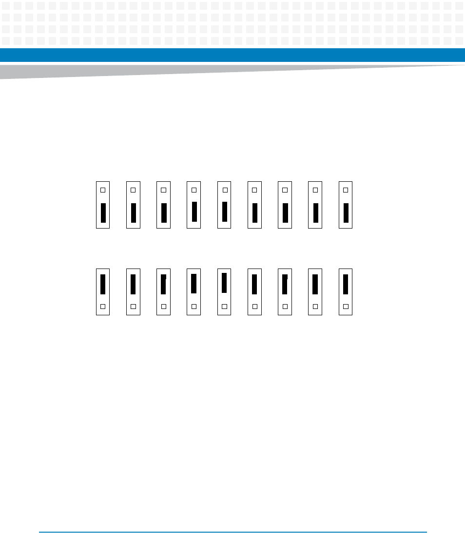
A jumper installed across pins 1 and 2 on all nine headers selects PMC1 for PMC I/O mode. A
jumper across pins 2 and 3 on all nine headers selects IPMC I/O mode.
1.5.3
PMC I/O Voltage Configuration
The onboard PMC sites may be configured to support 3.3V or 5.0V I/O PMC modules. To
support 3.3V or 5.0V I/O PMC modules, both PMC sites on the MVME6100 have I/O keying
pins. One pin must be installed in each PMC site and both PMC sites must have their keying pins
configured he same way. If both keying pins are not in the same location or if the keying pins
are not installed, the PMC sites will not function. Note that setting the PMC I/O voltage to 5.0V
forces the PMC sites to operate in PCI mode instead of PCI-X mode.
The VIO keying pins are the silver colored pins located either in the middle of each set of four
PMC site connectors or just in front of those connectors. They serve two functions on the
MVME6100: both as jumpers to select the PCIbus VIO signaling voltage for the PMC sites, and
as keys to permit mounting of PMC cards that are compatible with that VIO signaling voltage
Figure 1-4
PMC/IPMC Header Settings
J10
1
2
3
PMC1 P2 I/O for PMC Mode
J16
1
2
3
J15
1
2
3
J17
1
2
3
J18
1
2
3
J25
1
2
3
J26
1
2
3
J27
1
2
3
J28
1
2
3
J10
1
2
3
IPMC P2 I/O for IPMC Mode
J16
1
2
3
J15
1
2
3
J17
1
2
3
J18
1
2
3
J25
1
2
3
J26
1
2
3
J27
1
2
3
J28
1
2
3
(factory configuration)