Receiver analog, Receiver input buffer, Receiver analog –9 – Altera Stratix GX Transceiver User Manual
Page 27: Figure 2–6. serializer bit order
Altera Corporation
2–9
January 2005
Stratix GX Transceiver User Guide
Stratix GX Analog Description
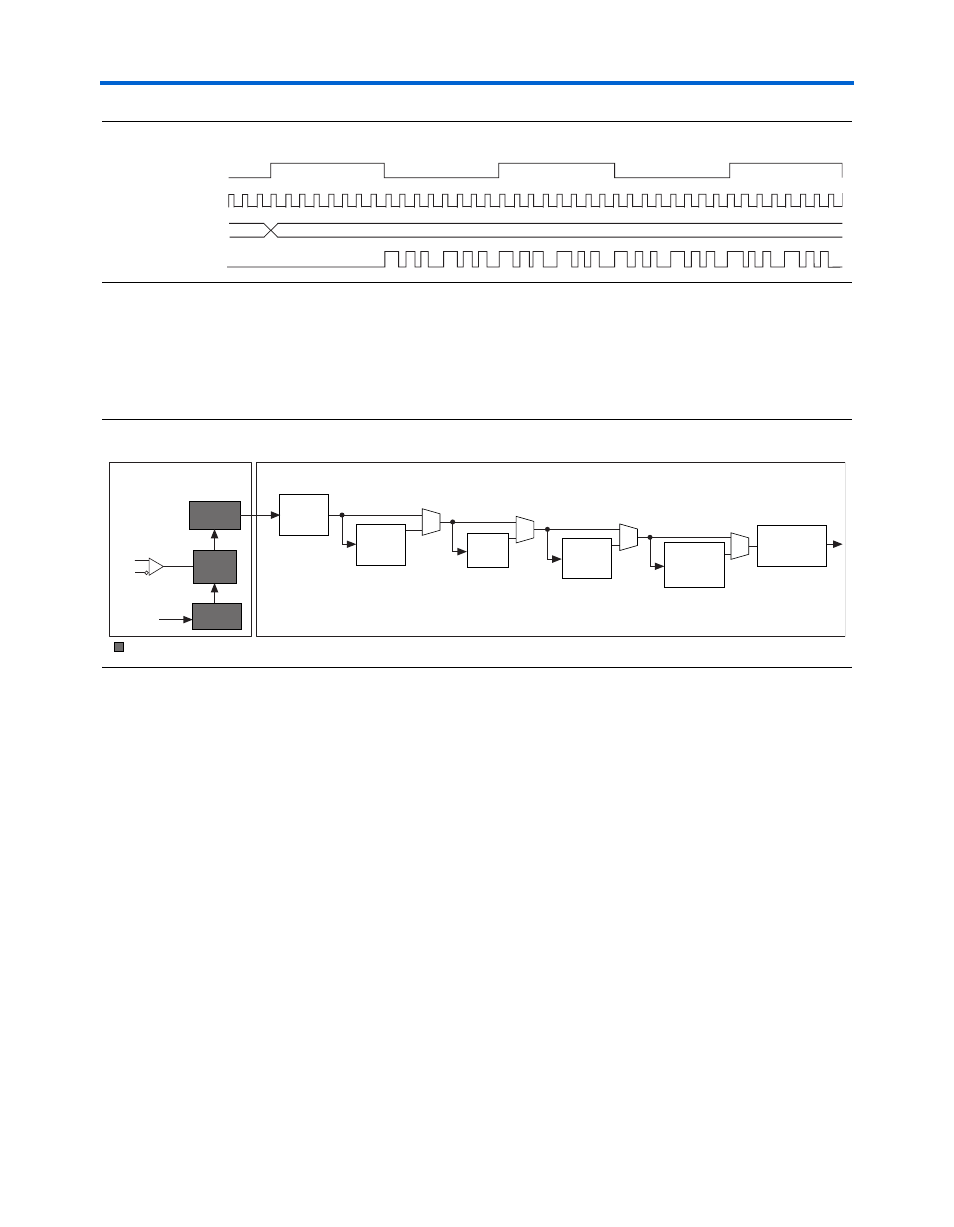
Figure 2–6. Serializer Bit Order
Receiver Analog
This section describes the receiver input buffer, the receiver PLL, the clock
recovery unit, and the deserializer.
shows the receiver analog
components.
Figure 2–7. Highlighted Block Diagram of the Receiver Analog Components
Receiver Input Buffer
The receiver input buffer contains internal termination and internal
equalization.
shows the structure of the input buffer. The input
buffer has programmable equalization that you can apply to increase the
signal integrity of the transmission line. The internal termination in the
receiver buffer can support AC and DC coupling with programmable
differential termination settings of 100, 120, or 150
Ω..
Parallel Clock
Serial Clock
Parallel Data (in Hex)
Serial Data Out
011 01 010
(x)
56
Deserializer
Word
Aligner
8B/10B
Decoder
Channel
Aligner
Byte
Deserializer
Phase
Compensation
FIFO Buffer
Reference
Clock
Rate
Matcher
Digital Section
Analog Section
Receiver
PLL
Clock
Recovery
Unit
Receiver