Altera External Memory PHY Interface User Manual
Page 34
3–18
Chapter 3: Functional Description—ALTMEMPHY (nonAFI)
ALTMEMPHY Signals
External Memory PHY Interface (ALTMEMPHY) (nonAFI) Megafunction User Guide
© January 2010
Altera Corporation
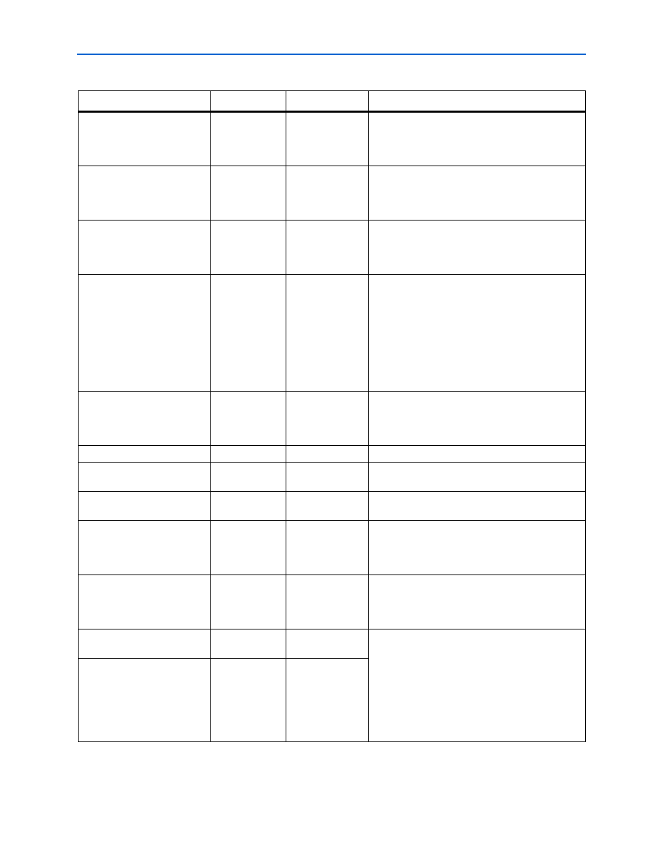
ctl_mem_cas_n_l
input
1
The column-address strobe signal from the
controller to the memory. Output during the low
half-period of the address and command clock and
driven by the memory controller.
ctl_mem_cke_h
input
MEM_IF_CS_
WIDTH
The clock-enable signal from the controller to the
memory. Output during the high half-period of the
address and command clock and driven by the
memory controller.
ctl_mem_cke_l
input
MEM_IF_CS_
WIDTH
The clock-enable signal from the controller to the
memory. Output during the low half-period of the
address and command clock and driven by the
memory controller.
ctl_mem_cs_n_h
input
MEM_IF_CS_
WIDTH
The chip-select signal from the controller to the
memory. For half-rate designs, always tie
ctl_mem_cs_n_h
high, as even with 2T
addressing, the chip select is only driven for the
second clock cycle, to allow an extra clock cycle of
setup time for the other address and command
signals. Output during the high half-period of the
address and command clock and driven by the
memory controller
ctl_mem_cs_n_l
input
MEM_IF_CS_
WIDTH
The chip-select signal from the controller to the
memory. Output during the low half-period of the
address and command clock and driven by the
memory controller.
ctl_mem_dqs_burst
input
1
Controls the DQS output enables of the DQS pins.
ctl_mem_odt_h
input
MEM_IF_CS_
WIDTH
The on-die termination signal from the controller to
the memory.
ctl_mem_odt_l
input
MEM_IF_CS_
WIDTH
The on-die termination signal from the controller to
the memory.
ctl_mem_ras_n_h
input
1
The row-address strobe signal from the controller
to the memory. Output during the high half-period
of the address and command clock and driven by
the memory controller.
ctl_mem_ras_n_l
input
1
The row-address strobe signal from the controller
to the memory. Output during the low half-period of
the address and command clock and driven by the
memory controller.
ctl_mem_rdata
output
LOCAL_IF_
DWIDTH
The ctl_mem_rdata signal is the captured,
resynchronized, and demultiplexed read data from
the ALTMEMPHY megafunction to the controller.
The ctl_mem_rdata_valid signal Indicates
when the ctl_mem_rdata is valid.
For more information, see
Between Read Commands and Read Data” on
page 3–47
.
ctl_mem_rdata_valid
output
1
Table 3–8. Datapath Interface for DDR2 and DDR SDRAM—nonAFI (Part 2 of 3)
(Note 1)
Signal Name
Type
Width
Description