Phy-to-controller interfaces, Phy-to-controller interfaces –4 – Altera External Memory PHY Interface User Manual
Page 20
3–4
Chapter 3: Functional Description—ALTMEMPHY (nonAFI)
PHY-to-Controller Interfaces
External Memory PHY Interface (ALTMEMPHY) (nonAFI) Megafunction User Guide
© January 2010
Altera Corporation
VT tracking is not required because the read strobe from the QDR II+/QDR II SRAM
memory is continuous. So all registers in the I/O to the read RAM path are clocked
using a clock that is derived from the QDR II+/QDR II SRAM read clock.
1
For more information about the QDR II+/QDR II SRAM signals, refer to
II+/QDR II SRAM Signals” on page 3–20
.
PHY-to-Controller Interfaces
The nonAFI’s autocalibration logic relies on the services of the memory controller to
perform its calibration writes, reads, and memory initialization, so it must have
control of the controller's local interface during the initial calibration stage. The
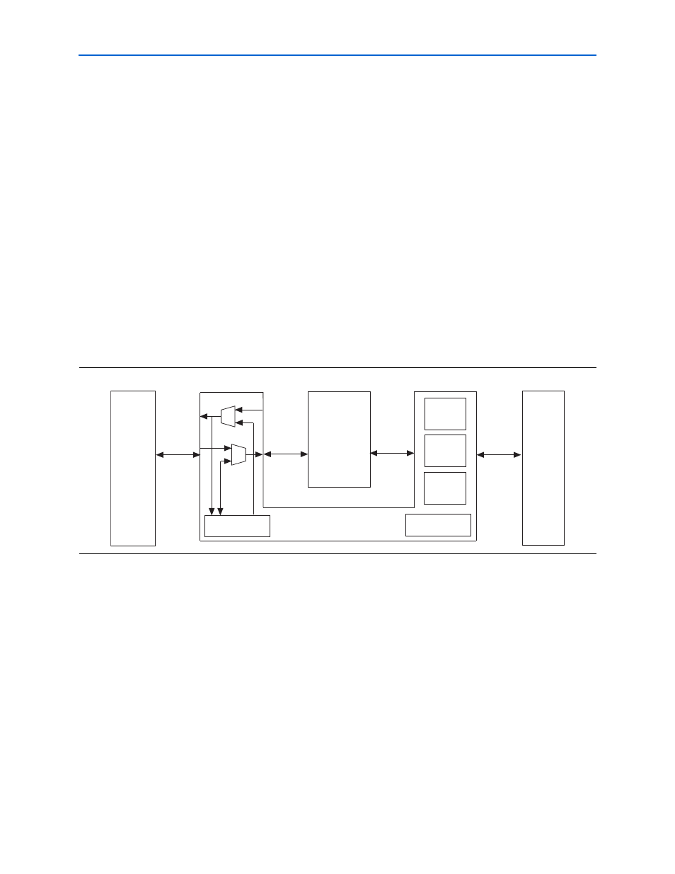
ALTMEMPHY megafunction has four interfaces that all must be connected
appropriately.
1
As an SRAM, the PHY for QDR II+/QDR II SRAM lacks most of the ctl_ and
local_
ports as you can use a driver that acts as a controller to generate read and
write commands and data in the QDR II+/QDR II SRAM PHY.
The four ALTMEMPHY interfaces, from left to right, are:
1. The local interface is the interface between the user logic and the memory
controller. The signals between user logic and the controller traverse through the
ALTMEMPHY megafunction. This can either be an Avalon
®
Memory-Mapped
slave interface or a Native interface. All the ports on this interface have their
names prefixed with local_; for example, local_init_done. During the initial
calibration period, the auto-calibration logic takes control of this interface and
issues the write and read requests that the memory controller requires. When the
calibration process is complete, control is handed back to the user logic and
normal operation occurs. The ALTMEMPHY megafunction auto-calibration logic
does not require any further access to the memory controller when the initial
autocalibration is complete.
Figure 3–3. The Four ALTMEMPHY Megafunction Interfaces
User logic
(or example
driver)
Auto-calibration
Memory
Controller
Clock & reset
management
ALTMEMPHY
Addr &
Cmd Path
Write path
Read path
P
o
rts named local_*
P
o
rts named ctl_*
P
o
rts named ctl_mem_*
P
o
rts named mem_*
External
Memory