4 digital inputs, 5 digital outputs, 1 supply voltage – Pilz PMCprimo DriveP.01/AA0/4/0/0/208-480VAC User Manual
Page 61: Digital inputs, Digital outputs, Supply voltage
Wiring
Operating Manual PMCprotego S12(C)
1002528EN02
61
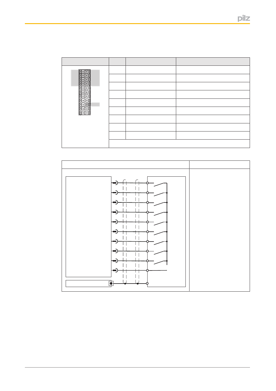
6.4
Digital inputs
Connector X30
Pin
Designation
Description
1
2
3
4
5
6
7
8
9
10
11
12
13
14
15
16
17
18
19
20
21
22
X30
1
SS1 Activate
Activate safety function SS1
2
I0
Activate safety function
3
I1
Activate safety function
4
I2
Activate safety function
12
I3
Activate safety function
13
I4
Activate safety function
14
I5
Activate safety function
15
I6
Activate safety function
20
SS1 SIL3/Reset
Input for SIL 3 and reset
Connector pin assignment
Input circuit
Digital input
1
I0
2
3
4
0V
12
24 V
I/O-GND
X30
I4
I3
I2
I1
I5
13
14
21, 22
SS1 Activate
15
I6
20
SS1 SIL3/Reset
Shield
Servo Amplifier
Shield
Shielded cable
Max. cable length: 30 m
24 VDC
Referenced to earth:
X30, Pin 21, 22 are linked
internally
Connection
6.5
Digital outputs
6.5.1
Supply voltage
The digital outputs need a 24 VDC supply.
}
When selecting the power supply, please refer to the requirements stated under “Tech
nical Details”.
}
The power supply must be able to bridge a power outage of 20 ms.
- PMCprimo DriveP.01/AA0/5/0/0/208-480VAC PMCprimo DriveP.12/AA0/4/0/0/208-480VAC PMCprimo DriveP.12/AA0/4/P/0/208-480VAC PMCprimo DriveP.03/AA0/4/0/0/208-480VAC PMCprimo DriveP.06/AA0/4/0/0/208-480VAC PMCprimo DriveP.24/ABB/4/0/0/208-480VAC PMCprimo DriveP.03/AB0/5/0/0/208-480VAC PMCprimo DriveP.06/AB0/2/0/0/208-480VAC PMCprimo DriveP.03/AB0/3/0/0/208-480VAC PMCprimo DriveP.06/AB0/3/0/0/208-480VAC PMCprimo DriveP.12/AB0/2/0/0/208-480VAC PMCprimo DriveP.12/ABC/4/P/0/208-480VAC PMCprimo DriveP.12/AB0/3/0/0/208-480VAC PMCprimo DriveP.03/AB0/2/0/0/208-480VAC PMCprimo DriveP.12/AAC/4/0/0/208-480VAC PMCprimo DriveP.24/AA0/5/0/0/208-480VAC PMCprimo DriveP.12/AA0/2/0/0/208-480VAC PMCprotego D.01/000/0/0/2/208-480VAC PMCprotego D.03/000/0/0/2/208-480VAC PMCprotego D.06/000/0/0/2/208-480VAC PMCprotego D.12/000/0/0/2/208-480VAC PMCprotego D.24/000/0/0/2/208-480VAC PMCprotego D.12/000/0/P/2/208-480VAC PMCprotego D.01/200/0/0/2/208-480VAC PMCprotego D.01/100/0/0/2/208-480VAC PMCprotego D.01/010/0/0/2/208-480VAC PMCprotego D.06/010/0/0/2/208-480VAC PMCprotego D.06/100/0/0/2/208-480VAC PMCprotego D.06/200/0/0/2/208-480VAC PMCprotego D.03/010/0/0/2/208-480VAC PMCprotego D.03/200/0/0/2/208-480VAC PMCprotego D.03/100/0/0/2/208-480VAC PMCprotego D.12/010/0/0/2/208-480VAC PMCprotego D.12/200/0/0/2/208-480VAC PMCprotego D.12/100/0/0/2/208-480VAC PMCprotego D.12/010/0/P/2/208-480VAC PMCprotego D.12/200/0/P/2/208-480VAC PMCprotego D.12/100/0/P/2/208-480VAC PMCprotego D.24/200/0/0/2/208-480VAC PMCprotego D.24/100/0/0/2/208-480VAC PMCprotego D.24/010/0/0/2/208-480VAC PMCprotego S1-2 PMCprotego S1-2-C