Pilz PMCprimo DriveP.01/AA0/4/0/0/208-480VAC User Manual
Page 49
Function description
Operating Manual PMCprotego S12(C)
1002528EN02
49
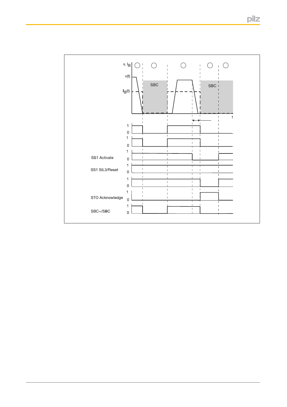
Timing diagram with the brake signal from the servo amplifier connected
Servo amplifier
ENABLE
Servo amplifier
BR+/BR-
STO / STO SIL3
A
B
C
D
E
∆SS1
-
Fig.: Safety function SBC
Legend:
}
State of the holding brake connected to the safety card during phases A … E:
–
A: Brake vented
–
B: Brake engaged (due to DISABLE on the servo amplifier)
–
C: Brake vented
–
D: Brake engaged (due to STO on the safety card)
–
E: Brake engaged (due to DISABLE on the servo amplifier)
}
Servo amplifier ENABLE: ENABLE signal on the servo amplifier
}
Servo amplifier BR+/BR: Brake on the servo amplifier
}
SS1 Activate: Input for safety function SS1
}
SS1 SIL3/Reset: Input for SIL3 and reset
}
STO / STO SIL3: Internal shutdown route STO and second shutdown route STO SIL3
}
STO Acknowledge: Output for feedback from safety function STO
}
SBC+/SBC: Brake control output
}
∆SS1: SS1 delay time
- PMCprimo DriveP.01/AA0/5/0/0/208-480VAC PMCprimo DriveP.12/AA0/4/0/0/208-480VAC PMCprimo DriveP.12/AA0/4/P/0/208-480VAC PMCprimo DriveP.03/AA0/4/0/0/208-480VAC PMCprimo DriveP.06/AA0/4/0/0/208-480VAC PMCprimo DriveP.24/ABB/4/0/0/208-480VAC PMCprimo DriveP.03/AB0/5/0/0/208-480VAC PMCprimo DriveP.06/AB0/2/0/0/208-480VAC PMCprimo DriveP.03/AB0/3/0/0/208-480VAC PMCprimo DriveP.06/AB0/3/0/0/208-480VAC PMCprimo DriveP.12/AB0/2/0/0/208-480VAC PMCprimo DriveP.12/ABC/4/P/0/208-480VAC PMCprimo DriveP.12/AB0/3/0/0/208-480VAC PMCprimo DriveP.03/AB0/2/0/0/208-480VAC PMCprimo DriveP.12/AAC/4/0/0/208-480VAC PMCprimo DriveP.24/AA0/5/0/0/208-480VAC PMCprimo DriveP.12/AA0/2/0/0/208-480VAC PMCprotego D.01/000/0/0/2/208-480VAC PMCprotego D.03/000/0/0/2/208-480VAC PMCprotego D.06/000/0/0/2/208-480VAC PMCprotego D.12/000/0/0/2/208-480VAC PMCprotego D.24/000/0/0/2/208-480VAC PMCprotego D.12/000/0/P/2/208-480VAC PMCprotego D.01/200/0/0/2/208-480VAC PMCprotego D.01/100/0/0/2/208-480VAC PMCprotego D.01/010/0/0/2/208-480VAC PMCprotego D.06/010/0/0/2/208-480VAC PMCprotego D.06/100/0/0/2/208-480VAC PMCprotego D.06/200/0/0/2/208-480VAC PMCprotego D.03/010/0/0/2/208-480VAC PMCprotego D.03/200/0/0/2/208-480VAC PMCprotego D.03/100/0/0/2/208-480VAC PMCprotego D.12/010/0/0/2/208-480VAC PMCprotego D.12/200/0/0/2/208-480VAC PMCprotego D.12/100/0/0/2/208-480VAC PMCprotego D.12/010/0/P/2/208-480VAC PMCprotego D.12/200/0/P/2/208-480VAC PMCprotego D.12/100/0/P/2/208-480VAC PMCprotego D.24/200/0/0/2/208-480VAC PMCprotego D.24/100/0/0/2/208-480VAC PMCprotego D.24/010/0/0/2/208-480VAC PMCprotego S1-2 PMCprotego S1-2-C