2 connector pin assignment, Connector pin assignment – Pilz PMCprimo DriveP.01/AA0/4/0/0/208-480VAC User Manual
Page 59
Wiring
Operating Manual PMCprotego S12(C)
1002528EN02
59
6.2
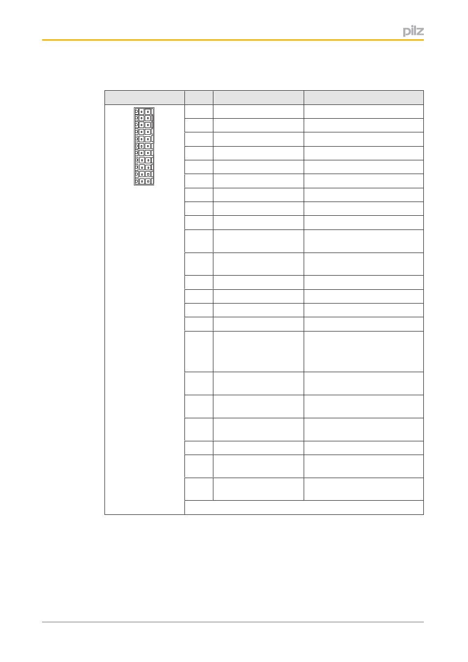
Connector pin assignment
X30
Pin
Name
Description
1
2
3
4
5
6
7
8
9
10
11
12
13
14
15
16
17
18
19
20
21
22
X30
1
SS1 Activate
Activate safety function SS1
2
I0
Activate safety function
3
I1
Activate safety function
4
I2
Activate safety function
5
STO Acknowledge
Status: STO activated
6
O0
Status: Safety function activated
7
O1
Status: Safety function activated
8
O2
Status: Safety function activated
9
O3
Status: Safety function activated
10
24 V Supply
Supply voltage for digital outputs
(24 VDC)
11
Encoder Supply
Supply voltage for external en
coder
12
I3
Activate safety function
13
I4
Activate safety function
14
I5
Activate safety function
15
I6
Activate safety function
16
Ready
Status: Safety card ready for op
eration and second output for
feedback from safety function
STO
17
SBC+
Output to control external brake
+
18
SBC
Output to control external brake
19
STO SIL3
Output, second STO shutdown
route for SIL 3
20
SS1 SIL3/Reset
Input for SIL 3 and reset
21
0 V Supply
1)
Supply voltage for digital outputs
(0 V)
22
0 V Encoder Supply
1)
Supply voltage for external en
coder (0 V)
1)
Pin 21, 22 linked internally
- PMCprimo DriveP.01/AA0/5/0/0/208-480VAC PMCprimo DriveP.12/AA0/4/0/0/208-480VAC PMCprimo DriveP.12/AA0/4/P/0/208-480VAC PMCprimo DriveP.03/AA0/4/0/0/208-480VAC PMCprimo DriveP.06/AA0/4/0/0/208-480VAC PMCprimo DriveP.24/ABB/4/0/0/208-480VAC PMCprimo DriveP.03/AB0/5/0/0/208-480VAC PMCprimo DriveP.06/AB0/2/0/0/208-480VAC PMCprimo DriveP.03/AB0/3/0/0/208-480VAC PMCprimo DriveP.06/AB0/3/0/0/208-480VAC PMCprimo DriveP.12/AB0/2/0/0/208-480VAC PMCprimo DriveP.12/ABC/4/P/0/208-480VAC PMCprimo DriveP.12/AB0/3/0/0/208-480VAC PMCprimo DriveP.03/AB0/2/0/0/208-480VAC PMCprimo DriveP.12/AAC/4/0/0/208-480VAC PMCprimo DriveP.24/AA0/5/0/0/208-480VAC PMCprimo DriveP.12/AA0/2/0/0/208-480VAC PMCprotego D.01/000/0/0/2/208-480VAC PMCprotego D.03/000/0/0/2/208-480VAC PMCprotego D.06/000/0/0/2/208-480VAC PMCprotego D.12/000/0/0/2/208-480VAC PMCprotego D.24/000/0/0/2/208-480VAC PMCprotego D.12/000/0/P/2/208-480VAC PMCprotego D.01/200/0/0/2/208-480VAC PMCprotego D.01/100/0/0/2/208-480VAC PMCprotego D.01/010/0/0/2/208-480VAC PMCprotego D.06/010/0/0/2/208-480VAC PMCprotego D.06/100/0/0/2/208-480VAC PMCprotego D.06/200/0/0/2/208-480VAC PMCprotego D.03/010/0/0/2/208-480VAC PMCprotego D.03/200/0/0/2/208-480VAC PMCprotego D.03/100/0/0/2/208-480VAC PMCprotego D.12/010/0/0/2/208-480VAC PMCprotego D.12/200/0/0/2/208-480VAC PMCprotego D.12/100/0/0/2/208-480VAC PMCprotego D.12/010/0/P/2/208-480VAC PMCprotego D.12/200/0/P/2/208-480VAC PMCprotego D.12/100/0/P/2/208-480VAC PMCprotego D.24/200/0/0/2/208-480VAC PMCprotego D.24/100/0/0/2/208-480VAC PMCprotego D.24/010/0/0/2/208-480VAC PMCprotego S1-2 PMCprotego S1-2-C