Seal-end main bearing, Crankshaft seal inspection and replacement, Replacement – Carrier 5F User Manual
Page 34: 5f,h open-drive compressors
Attention! The text in this document has been recognized automatically. To view the original document, you can use the "Original mode".
HEATING A COOLING
5F,H
Open-Drive Compressors
BEARING
PULLER
SHOULDER
N
DIRECTION OF PULL
•SEAL HOUSING
HOUSING PILOT
TOP PLATE
CRANKCASE BEARING HOUSING
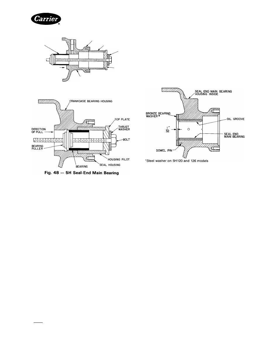
Fig. 47 — Seal-End Main Bearing (5F40, 60)
1. Position bearing so chamfered edge enters bearing
housing first, oil holes in bearing and housing are
aligned, and bearing relief groove is at top.
2. Pull bearing into housing (Fig. 49). Edge of bearing
should be 1/32-in. below surface of bronze bearing
washer.
Look through oil pressure regulator opening to
check oil passage for blockage.
Blow out oil groove in bearing housing and oil lines
(if any) to it.
3.
Fig. 49 — Seal-End Main Bearing Positioning
REASSEMBLY — Install the new bearing inserts.
Assemble bearing housing on crankshaft, hut do not
tighten
the
hollow-cup
setscrew.
Install
crankshaft,
center main bearing and housing, and pump-end main
bearing assembly. Tighten bolts holding the pump-end
bearing assembly. Rotate crankshaft while tightening
setscrew on center main bearing housing. Setscrew should
tighten fully without any binding of crankshaft. If bind
ing occurs, shim the opposite side of bearing housing,
using .001-in. shim stock.
Seal-End Main Bearing
DISASSEMBLY AND INSPECTION — With crank
shaft removed, use a bearing puller with a shouldering
device to remove and install seal-end main bearings
(Fig. 47 and 48). Bearing pullers and sleeve pullers are
available from the Robin Air Manufacturing Company,
Montpelier, Ohio.
Inspect bearing and bearing housing for tolerances
shown in Table 11.
REASSEMBLY — Remove any burrs and clean bearing
housing before replacing bearing. Lubricate outside
of bearing with heavy grease.
Crankshaft Seal Inspection and Replacement
— The crankshaft seal in all current 5F,H compressors
is a rotating, bellows-type seal. This seal is the service
replacement for all earlier seal assemblies. Figure 50
shows Types I and II of this design (5F20 through 5H126
compressors).
IMPORTANT; Do not attempt to repair or replace
seal components. Replace complete seal assembly
with current rotating-bellows-type assembly. Do not
disassemble bellows assembly of service replace
ment seal.
BEFORE INSTALLING SEAL
1. Pump-end bearing head must be in place for proper
positioning of seal on crankshaft.
2. Be sure shaft extension and edges of keyway are free
of sharp edges and nicks. Also, shaft must be clean and
free of rust. Polish shaft with crocus cloth.
3. Check seal assembly for proper bellows placement
and cleanliness.
4. Apply compressor oil to seal assembly and crank
shaft, completely saturating bellows and carbon ring.
INSTALLATION — Refer to Fig. 51 for procedure.
Manufacturer reserves the right to discontinue, or change at any time, specifications or designs without notice and without incurring obiigations.
Book [2
PC 111
Catalog No 530-526
Printed i n U S A
Form5F,H-11SI
Pg 34
2-86
Replaces: 5F,H-9SI
Tab 12a
For replacement Items use Carrier Specified Parts.