5f,h open-drive compressors – Carrier 5F User Manual
Page 12
Attention! The text in this document has been recognized automatically. To view the original document, you can use the "Original mode".
HEATING A COOLING
5F,H
Open-Drive Compressors
INSTALL CRANKCASE HEATER — Wire heater to
relay or set of normally closed auxiliary contacts on
compressor starter to de-energize it when compressor
is operating.
Remove rubber plug from crankcase heater casing
(Fig. 1-8), and insert heater element entirely into casing.
Element should fit snugly, not loosely. Wire to comply
with applicable electrical codes.
When crankcase heater is installed, system can be
operated on single pumpout cycle, unless used with a DX
cooler.
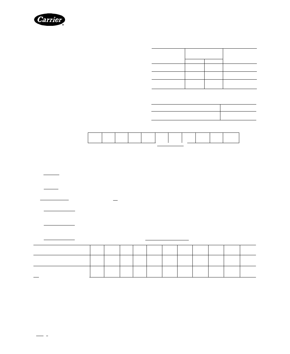
Table 2 lists crankcase heater packages. Table 3 shows
corresponding relays. Use of 2 heaters on a 5H80 or
5H120 compressor requires only one relay.
Control circuit voltage determines relay coil voltage.
This voltage must be specified when ordering relays.
See Accessory Compressor Crankcase Heater Instal
lation Instructions for additional information.
Table 2 — 5F,H Compressor Crankcase
Heater Package
COMPRESSOR
ELECTRICAL
CHARACTERISTICS
PACKAGE NO.
Volts
Watts
5F20,30,40,60
115
230
100
100
-5-F-20—381
-5-F-20—391
5H40,46,60,66
115
230
200
200
-5-H-40—381
-5-H-40—391
5H80,86,120,126
115
230
200
200
-5-J-40—281
-5-J-40—291
Table 3 — Crankcase Heater Relay (60 Hz)
CONTROL CIRCUIT VOLTAGE
PART NO.
115
HN61AJ-101
208/230
HN61AJ-108
Table 4 — Physical Data
COMPRESSOR
UNIT
AND
CONDENSING UNIT
5F20
5F30
5F40
5F60
5H40
5H46
5H60
5H66
5H80
5H86
5H120
REFRIGERANT
R-12, R-22, R-502
COMPRESSOR DATA
Maximum Rpm
Minimum Rpm
Minimum Rpm Capacity
Control
600
700
800
1750
400 (required for proper lubrication)
900
800
800
900
900
1100
1100
900
900
Number of Cylinders
Bore (in.)
Stroke (In.)__________
2
2'/2
2
3
2'/2
2
4
2'/2
2
6
2'/2
2
4
3V
a
2%
4
3’/4
3%
6
3%
2%
6
3'/4
3y,6
8
3'/4
2%
8
3'/4
3V,6
12
3'/4
2%
12
3'/4
3V,6
Compressor
Connections
(in. O.D.)
Suction
Discharge
VA
Ve
IVs
1%
V/e
1%
2Ve
VA
2%
2'A
2%
2'A
3'A
3'A
3'A
3'A
3'A
3'A
3'A
3'A
4'/e
4'A
4'A
4'A
Oil Charge* (pt)
(See Notes)
Normal Oil Pressure*
Oil Flow Rate (gpm)___________
55
12
13
18
18
21
21
41
45-55 psig above suction pressure —
1 5_____________I_____________________ 3_0___________
41
61
61
4.5
Oil Safety Switch
Cut-in (psig)
(See Notes
Cutout (psig)
3 and 4)
15 - 19.5
11 - 15
High-Pressure Switchf
Cutout Range
Differential (psi)
Factory Setting (psig)
150-395 (adjustable) nominal
60-150 (adjustable)
Cutout, 300 ± 15, Cut-in, 210 ± 10
Low-Pressure Switchf
Cutout Range
Differential (psi)
Factory Setting (psig)
20 in Hg vac to 60 psig (adjustable)
60-90 (adjustable)
Cutout, 50 ± 4; Cut-in, 120 ± 6
Low Side Maximum Pressure
245 psig
CONDENSER DATA
5F20f
5F30f
5F40
5F60
09RH-
027
09RH-
043
09RH-
054
09RH-
070
09RH-
084
09RH-
097
09RH-
127
Maximum Refrig-
R-12
40 4
50 7
79.4
89 6
154
212
263
238
282
358
475
erant Storage
R-22
37 2
46.4
72 8
82 0
139
193
239
216
257
327
432
Capacity** (lb)
R-502
38.2
47.9
75.0
84.6
145
199
248
223
265
337
447
Minimum Refrig-
R-12
20
30
140
160
37.0
41 0
51 0
51 0
78
100
126
erant Operating
R-22
1 8
27
127
14.5
33.0
37 0
46.0
46 0
71
91
114
Charge (ib)
R-502
1.9
2.9
13.1
15.0
34.4
38.2
47.3
47.3
73
94
118
Maximum Operating Pressure
Refrigerant Side
Water Side
150 psig
385 psig
250 psig
‘Nominal oil pressures shown in Physical Data table are above suction
pressure, i e , pressure differential between suction pressure and dis
charge pressure of oil pump
tSee Table 5 for typical pressure switch settings
fShell-and-coil condensers All other 5F,H condensers are shell-and-
tube
‘‘Condenser storage capacity 80% filled with liquid refrigerant at 90 F
NOTES:
1 Oil flow rate is the nominal oil pump capacity
2 The following oil (or equivalents) are specified for use in 5F,H
compressors
5F20 and 30: Witco Chemical Co — Suniso 4GS
5F40-5H126: Witco Chemical Co. — Suniso 3GS
Texaco, Inc — WF32
Shrieve Chemical Co — Zerol 150 (synthetic)
3 Differential switch (oil safety switch) has time delay of 30 to 60 seconds
4 Oil safety switch has manual reset
Book 12
PC 111
Catalog No 530-526
Printed inUS A
Form5F,H-11SI
Pg12
2-86
Replaces: 5F,H-9SI
Tab 12a
Manufacturer reserves the right to discontinue, or change at any time, specifications or designs without notice and without incurring obligations.
For replacement items use Carrier Specified Parts.