5f,h open-drive compressors – Carrier 5F User Manual
Page 26
Attention! The text in this document has been recognized automatically. To view the original document, you can use the "Original mode".
HEATING A COOLING
5F,H
Open-Drive Compressors
Leaf-type check valve on 5F40 and 60 and 5H40, 46,
60, 66, 80, and 86 compressors is accessible through, and
located at top center of, handhole cover opening.
Remove check valves and check to see that flutter
valve or leaf does not stick, and that it seats tightly.
CHECK VALVE
LEAF TYPE
Fig. 28 — Oil Return Check Valves
OIL SEPARATOR
IMPELLER
\
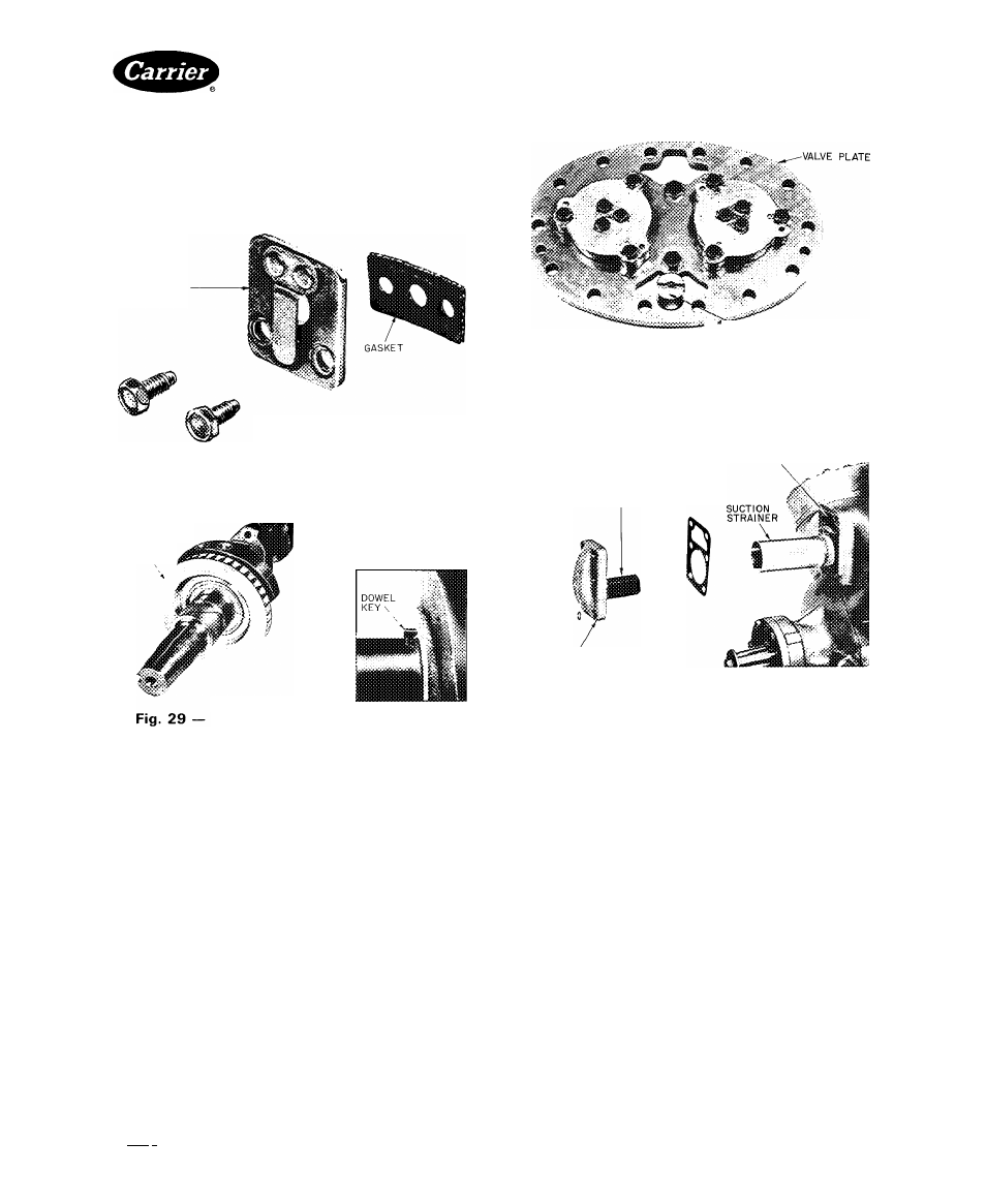
Centrifugal Oil Separator Impeller
CENTRIFUGAL OIL SEPARATOR on 5HI20 and
126, mounted on crankshaft (Fig. 29), returns oil to
compressor
crankcase.
To
remove
or
replace
oil
separator, see Crankshaft Inspection and Service.
OIL FILTER SCREEN (Fig. 21) in compressor crank
case is accessible through handhole cover or bottom
plate. Remove and inspect it for holes, then clean it with
solvent and replace.
Pressure-Relief Valves — When pressure differ
ential between high- and low-pressure sides exceeds 350
± 35 psi (5F60: 400 ± 40 psi), pressure-relief valve bleeds
refrigerant from high to low side.
Check relief valves for evidence of leaking. Change if
defective or if valve has ever opened due to excessive
pressure.
5F60 COMPRESSORS — Internal relief valve screws
into crankcase and projects up through left cylinder-
bank valve plate (Fig. 30). Use a standard socket-type
screwdriver to remove and replace valve.
¡^‘'^PRESSURE RELIEF VALVE
(SEE NOTE)
NOTE: The pressure-relief valve is not part of the valve plate
assembly The valve mounts in the crankcase in the left side
cylinder deck (looking at pump end). The valve plate opening
outlined, slips over the pressure-relief valve when assembled
Fig. 30 — Pressure Relief Valve (5F60)
DISCHARGE MANIFOLD
PRESSURE RELIEF VALVE
IP*
SUCTION
AND
DISCHARGE
MANIFOLD COVER
Fig. 31 — Pressure Relief Valve and
Suction Strainer (5H40, 46, 80, 86)
5H40, 46, 80 AND 86 COMPRESSORS — Pressure-
relief valve is located on suction and discharge manifold
cover (Fig. 31).
5H60 AND 5H66 COMPRESSORS — Relief valve is
located in wall between suction and discharge manifolds.
Remove discharge manifold for access to relief valve.
Use a standard 1-1/2in. socket to remove and install
the valve.
5H120 AND 5H126 COMPRESSORS are equipped
with external relief valve mounted on bypass line between
suction shutoff valve and discharge manifold. To
remove valve, remove bolts from flanges on either side
of valve.
Suction Strainer — To withdraw strainer on 5F20
and 40 and 5H40 and 46 compressors, remove suction
and discharge manifold cover on seal end of compressor.
On 5F30 compressor, remove suction service valve. On
5F60 and 5H60 and 66 compressors, remove suction
manifold and withdraw 2 strainers. On 5H80 and 86
compressors, remove suction manifold cover.
On 5H120 and 126 compressors, remove one suction
manifold plate at a time so as not to disturb position of
Manufacturer reserves the right to discontinue, or change at any time, specifications or designs without notice and without incurring obligations.
Book|2
PC111
Catalog No 530-526
PrintedinUSA
Form5F,H-11SI
Pg 26
2-86
Replaces: 5F,H-9SI
Tab 12a
replacement Items use Carrier Specified Parts.