5f,h open-drive compressors – Carrier 5F User Manual
Page 29
Attention! The text in this document has been recognized automatically. To view the original document, you can use the "Original mode".
HEATING A COOLING
5F,H
Open-Drive Compressors
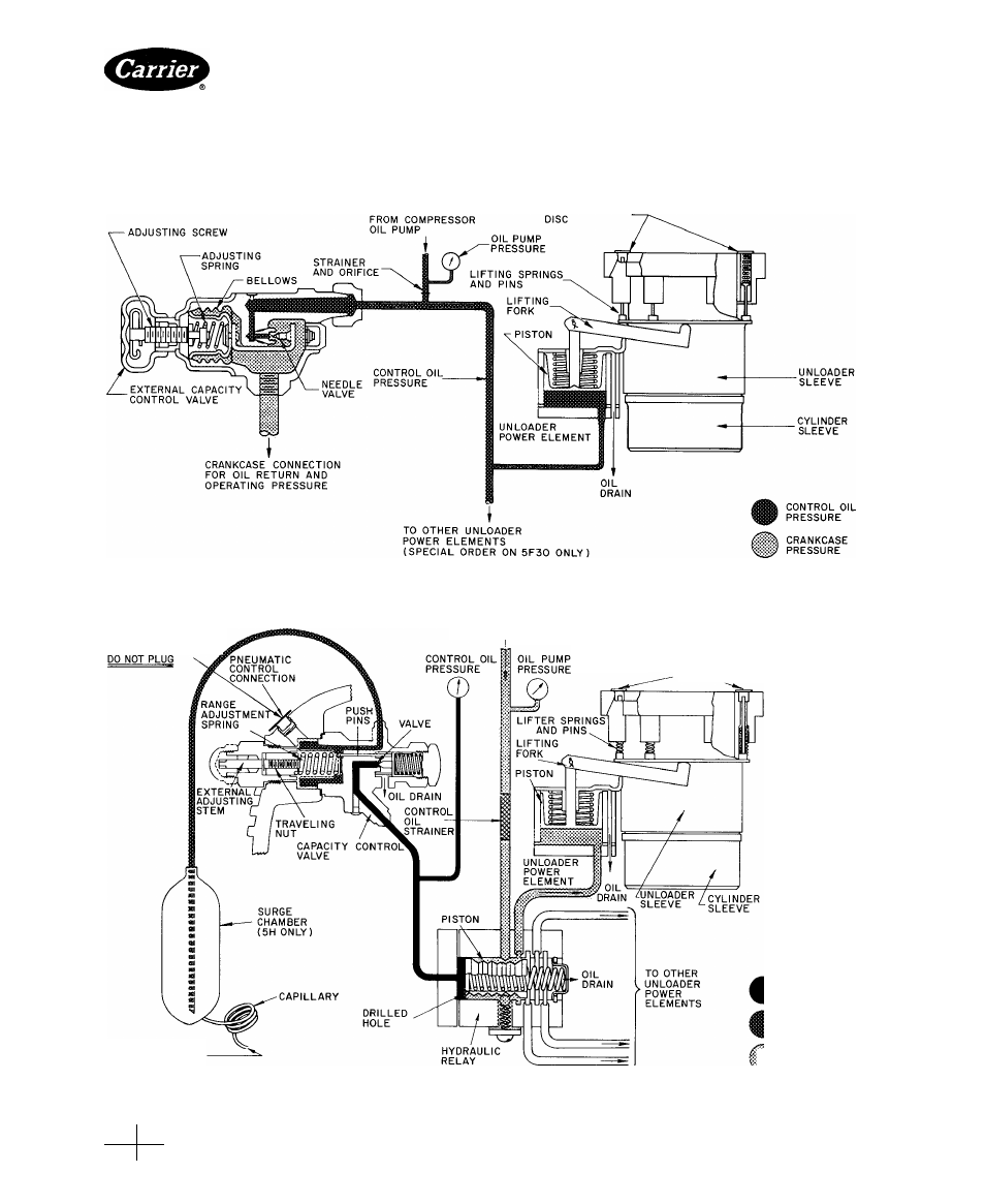
of its total capacity. Figure 17 shows the sequence and
number of cylinders that unload with each step.
Capacity control unloader systems consist of 4 major
components:
1. A capacity control valve, which increases or
decreases control oil pressure to the hydraulic relay
piston proportionally when the suction pressure from
the crankcase rises or falls.
SUCTION VALVE
Fig. 36 — Capacity Control (5F20, 5F30)
IF PNEUMATIC CONTROL
IS NOT USED. THIS
PORT MUST BE VENTED
FROM
COMPRESSOR
OIL PUMP,
SUCTION VALVE
DISC -
FROM
CRANKCASE
PRESSURE
CONTROL
OIL
PRESSURE
CRANKCASE
PRESSURE
OIL
PUMP
PRESSURE
Fig. 37 — Capacity Control Operation (5F40. 60; 5H40, 60. 66, 80 and 86)
Manufacturer reserves the right to discontinue, or change at any time, specifications or designs without notice and without incurring obiigations.
PC 111
Catalog No 530-526
Printed inUS A
Form5F,H-11SI
Pg 29
2-86
Replaces: 5F,H-9SI
For replacement items use Carrier Specified Parts
Book
2
Tab
2
a