Scheduled maintenance, 5f,h open-drive compressors – Carrier 5F User Manual
Page 17
Attention! The text in this document has been recognized automatically. To view the original document, you can use the "Original mode".
HEATING «COOLING
5F,H
Open-Drive Compressors
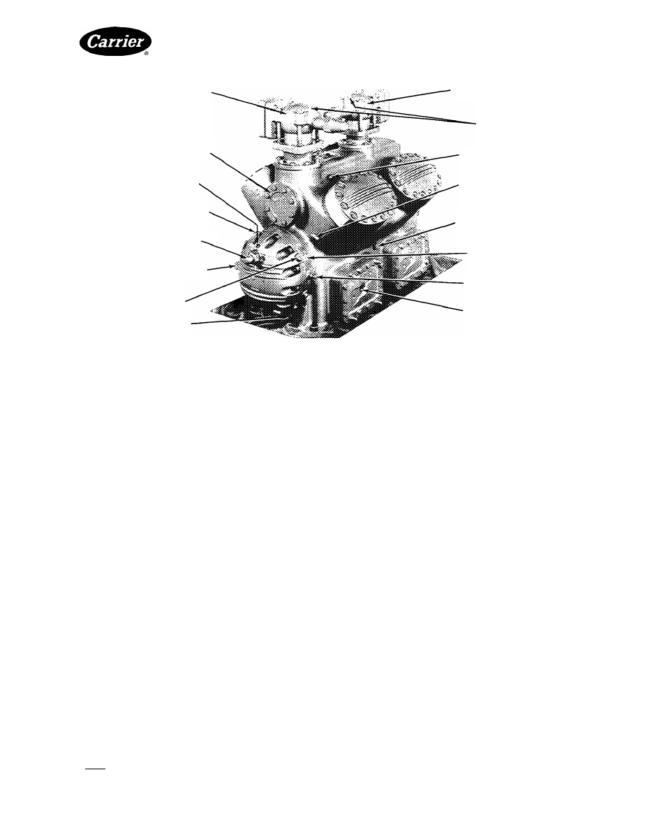
SUCTION
SHUTOFF
VALVE
3-1/8“ ODF
SUCTION MANIFOLD COVER
(REMOVE FOR ACCESS TO
SUCTION STRAINER)
PNEUMATIC
CONTROL
CONNECTION 1/4“ IPS
OPENING
TO
CRANKCASE
1/4" IPS
CAPACITY
CONTROL
VALVE
ADJUSTING STEM
CONTROL
OIL
STRAINER
PLUG 5/8“-18
OIL
FILLER
PLUG
CRANKCASE DRAIN
DISCHARGE
SHUTOFF
VALVE
3-1/8“ ODF
GAGE
CONNECTIONS
1/4“ IPS
HIGH-PRESSURE
CONTROL
CONNECTION 1/4" IPS
LOW-PRESSURE
CONTROL
CONNECTION 1/4“ IPS
CENTER MAIN BEARING
RETAINING SCREW ACCESS
OIL PUMP
ROTATION ARROW (TAG)
CONTROL OIL PRESSURE
OIL LEVEL SIGHT GLASS
Fig. 18 — 5H80, 86 8- Cylinder Compressor
m
SCHEDULED MAINTENANCE
5F,H compressor and condensing units provide long
life and dependable service when properly operated and
regularly maintained. Establish a maintenance schedule
based on factors such as operating hours, load eonditions
and water quality. Maintenance schedules listed in this
section are offered as guides. Modify them as needed to
satisfy individual machine requirements.
Check Lubrication System — Always check com
pressor oil level before starting unit. If oil is required,
record date and amount added. Refer to Fig. 1-8 for loca
tion of oil filter plug. Table 4 shows specified types and
quantities of oil.
Use of accessory oil separator requires additional oil.
Oil level and separator float valve movement during
initial compressor operation should agree with instruc
tions furnished with the oil separator.
OIL FILTER MAINTENANCE — A bleed-type, high-
pressure, disposable filter is available as an accessory
for 5H40 through 5H86 eompressors (Fig. 19). Replace
oil filter after the first 50 hours of operation, or whenever
the oil is changed or becomes dirty.
Check yearly for clogged filter, indicated by a greater
than normal difference between oil pressure ahead of
fdter and after filter. When this difference exceeds 5 psig,
change filter as follows;
1. Close oil-line shutoff valves on each side of filter
(Fig. 19).
2. Disconnect oil lines at filter connections.
3. Loosen filter bracket; remove and replace filter body.
Refer to Accessory Oil Filter Instructions for
additional information.
The full-flow oil filter on 5H120 and 5H126 com
pressors contains a replaceable cartridge. Replaee the
filter cartridge after the first 100 hours of compressor
operation. After the initial filter change, check yearly for
filter clogging. If the pressure difference across the filter
exceeds 5 psig, pump down the compressor and then
remove the cartridge. Figure 20 illustrates complete
filter assembly.
Manufacturer reserves the right to discontinue, or change at any time, specifications or designs without notice and without incurring obligations.
Book|2
PC111 Catalog No 530-526 PrintedinUSA
Form5F,H-11SI Pg17 588
2-86 Replaces: 5F.H-9SI
For replacement items use Carrier Specified Parts
Tab 2a