Connecting rods and pistons, 5f,h open-drive compressors – Carrier 5F User Manual
Page 28
Attention! The text in this document has been recognized automatically. To view the original document, you can use the "Original mode".
HEATING A COOLING
5F,H
Open-Drive Compressors
To reassemble:
1. Rotate crankshaft to position piston at top center.
2. Lubricate piston rings and beveled surface at lower
edge of cylinder sleeve.
3. Stagger ring gaps around piston.
4. With turning motion, work sleeve over piston and
rings. Compress and align each ring with beveled edge
of sleeve.
5. Seat sleeve in suetion manifold partition and cylinder
deck recess.
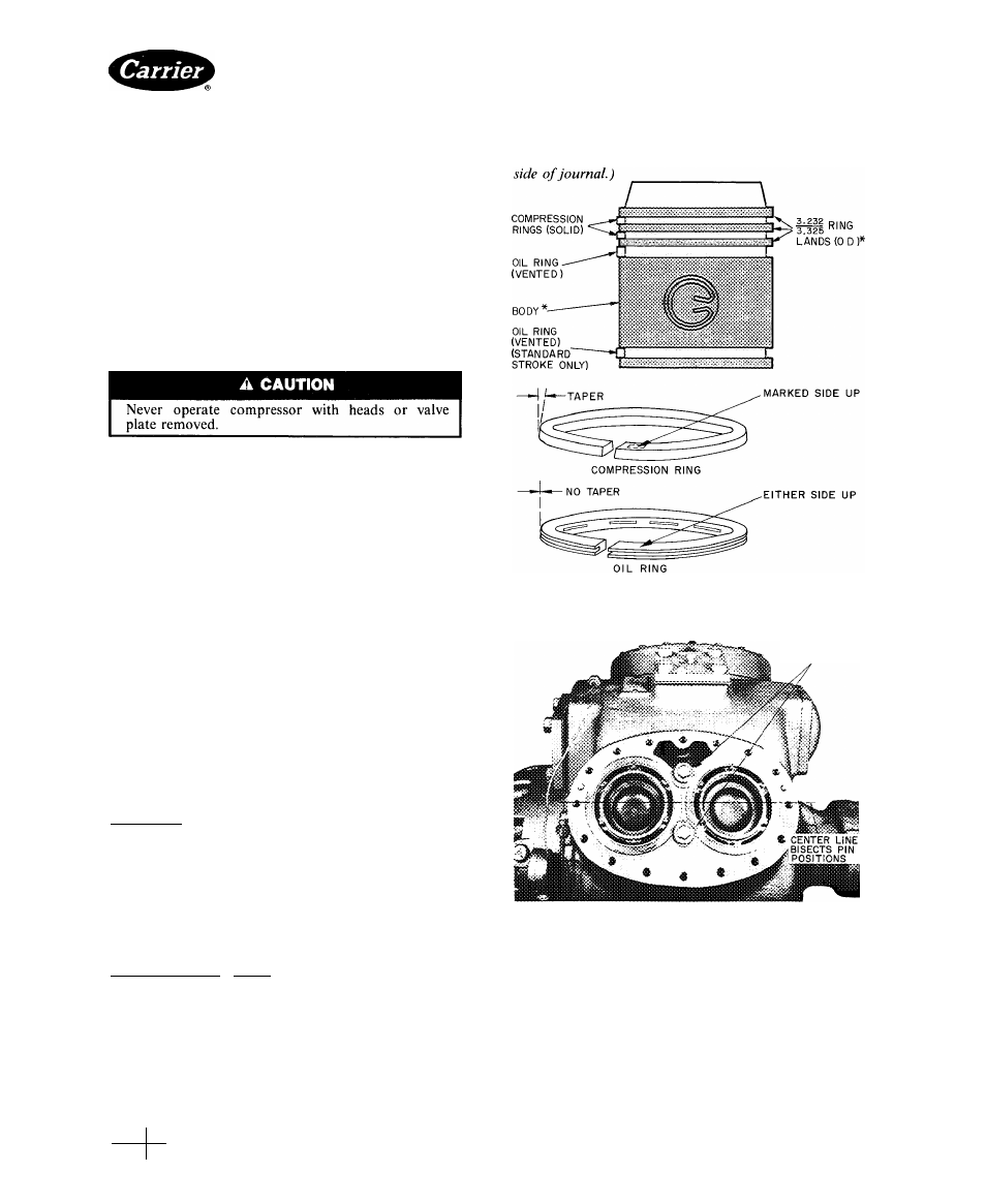
6. Rotate sleeve so that any 2 valve lifter-pin holes lie
equal distances from longitudinal axis of compressor
(Fig. 35). In this position, lifter pins line up with
suction valve springs.
install cap so chamfered sides are against radius of
crankpin. (Small knobs on rod and caps must be on same
Connecting Rods and Pistons
REMOVAL — Remove cylinder head, valve plate and
handhole cover or bottom plate to gain access to rods
and pistons.
Remove connecting rod caps (Fig. 22). Label caps and
rods so they may be reinstalled in same places on crank
shaft. Remove cylinder sleeve, connecting rod and piston
assembly as a unit by pushing assembly up through
cylinder deck. Do not allow piston to come up through
top of sleeve during removal process. Remove retaining
rings and piston pins to disassemble connecting rods from
pistons. Remove rings.
Keep each individual connecting rod and piston
assembly together to aid reassembly. Check all parts
and crankpin journals for wear (Table 11).
INSPECTION
AND
REPLACEMENT
Attach
con
necting rods to pistons with piston pins and lock in place
with retaining rings. Piston pins are selectively fitted for
a push fit; reassemble in the piston from which they
were removed. Place piston pin retaining rings, with gap
on side, on piston (Fig. 34). They should be tight
enough to inhibit rotation under finger pressure.
Check Rings
1. Check ring gap by inserting each ring separately in
cylinder approximately 3/8in. from top. Ring gap
should be between .007 and .017 inches.
2. Install compression rings on piston with side marked-
top toward piston head. Install oil rings either side up.
3. Stagger ring gaps around piston.
4.
Measure side clearance between ring and piston
(approximately .001 inch). Check rings for free action.
Check Rod Bearing Inserts (Fig. 22) — If bearing inserts
are damaged and crankshaft is not worn, it is only
necessary to replace inserts. Do not file bearing caps.
Place the inserts in connecting rod and connecting rod
caps so knobs on inserts fit into notches on rod cap.
Lubricate insert bearing and crankpin freely before
installing caps.
Install cylinder sleeve, eonnecting rod and piston
assembly at the same time. Turn connecting rod, and
'See Table 11 for piston diameters.
Fig. 34 — Aluminum Long-Stroke Piston Details
CAP
SCREWS
AND WASHERS
Fig. 35 — Position of Cylinder Sleeves
Capacity Control Operation — All 5F,H series
compressors, except 5F20 and 30 units, include hydraulic
capacity control unloader systems as standard equip
ment. (Field-installed accessory unloader packages are
available for the 5F20 and 30.) The unloader system
activates
and
deactivates
the
compressor’s
cylinder
banks, by permitting suction valves to seat or preventing
them from doing so, in response to changing load de
mands. Capacity control unloaders can reduce a unit’s
actual operating capacity by steps down to as little as 25%
Manufacturer reserves the right to discontinue, or change at any time, specifications or designs without notice and without incurring obligations.
PC111
Catalog No 530-526
PrintedinUSA
Form5F.H-11SI
Pg 28
2-86
Replaces: 5F.H-9SI
For replacement items use Carrier Specified Parts
Book
2
Tab
2a