5f,h open-drive compressors – Carrier 5F User Manual
Page 23
Attention! The text in this document has been recognized automatically. To view the original document, you can use the "Original mode".
#
HEATING A COOLING
5F,H
Open-Drive Compressors
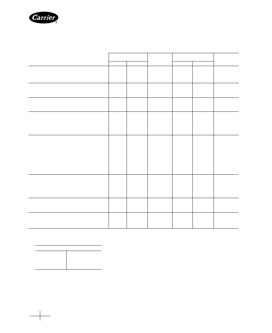
Table 11 — Wear Limits; 5F,H Compressors
COMPRESSOR
5F20,30,40,60
COMPRESSOR PART
Factory
Maximum
Factory
Maximum
Tolerances (in.)
Allowable
Tolerances (in.)
Allowable
Max
Min
Wear (in.)
Max
Min
Wear (in.)
SEAL END
Main Bearing Diameter — 5F20, 30
1 6264
1 6250
002
2 6278
2 6250
001
— 5F40, 60
2 0636
2.0618
.001
—
—
—
Journai Diameter — 5F20, 30
1 6240
1 6233
.003
2 6235
2 6225
002
— 5F40, 60
2 061
2 060
.002
—
—
—
PUMP END
Main Bearing Diameter — 5F20, 30
1 6264
1.6250
002
2 2530
2 2502
001
(Assembieid) — 5F40, 60
1 6264
1.6250
001
—
—
—
Journal Diameter
1 6240
1 6233
.002
2 249
2 248
002
CENTER (5H80,86,120,126)
Main Bearing Diameter
—
—
—
2 6264
2 6250
001
Main Bearing Thickness
—
—
—
—
.0942
001
Journal Diameter
_
—
—
2 6235
2 6225
002
CONNECTING ROD
Bearing Diameter
1 6255
1 6245
002
2.2505
2.2495
002
Bearing Thickness
—
06225
001
—
06225
.001
Crankpin Diameter
1 6240
1 6233
003
—
2 248
002
Seal End Bearing Washer Thickness
131
.129
*
188
186
Seal End Thrust Washer Thickness
157
155
*
188
186
*
Pump End Bearing Washer Thickness
131
129
*
188
186
CYLINDERS
Bore
2 501
2.500
003
3 2515
3 2505
003
Piston Diameter —Steel, Standard Stroke
—
2.4980
003
3 2485
3 2480
003
— Aluminum, Long Stroke
Body
—
—
—
3 241
3 240
003
Ring Groove (OD)
_
—
3 235
3 232
003
Piston Pin Diameter
—
7498
001
—
.9998
001
Piston Pin Bushing
7500
—
001
1.000
—
001
Piston Ring End Gap (compression and oil)
009
004
.030
.017
007
030
Piston Ring Side Clearance
Compression Side
0015
0005
003
0015
0005
003
Oil Side
0012
0002
0012
0002
OIL PUMPt
Axial Clearance
0015
.0005
0025
0015
0005
0025
Drive Shaft Diameter
4361
4356
—
4361
4356
—
Drive Shaft Bushing Diameter (10)
4375
—
—
.4375
4370
—
Drive Shaft Diameter (5H120 & 126)
—
—
—
6250
.6240
—
Drive Shaft Bushing Diameter
6270
6260
_
(ID — 5H120 & 126)
SUCTION VALVE
Suction Valve Disc
005
(depth of wear below face)
Suction Valve Seat
—
012
002
—
012
002
DISCHARGE VALVE
Discharge Valve Disc
005
005
(depth of wear below face)
Discharge Valve Seat
—
012
.002
—
012
002
5H40,46,60,66,80,86,120,126
•Replace thrust and bearing washers when end clearance
exceeds maximum listed
CRANKSHAFT END CLEARANCE (In.)
5F20-5F60
011 to 035
5H40,46
010 to 036
5H60,66
011 to 037
5H 80,86
014 to 042
5H120,126
014 to 044
tReturn assemblies for factory exchange
#
Manufacturer reserves the right to discontinue, or change at any time, specifications or designs without notice and without Incurring obligations.
Book 2
PC 111
Catalog No 530-526 PrintedinUSA Form5F,H-11SI
Pg 23
2-86
Replaces: 5F,H-9SI
Tab
2a
For replacement items use Carrier Specified Parts.