Service instructions, Service notes, Lubrication system – Carrier 5F User Manual
Page 19: 5f,h open-drive compressors
Attention! The text in this document has been recognized automatically. To view the original document, you can use the "Original mode".
HEATING A COOLING
5F,H
Open-Drive Compressors
#
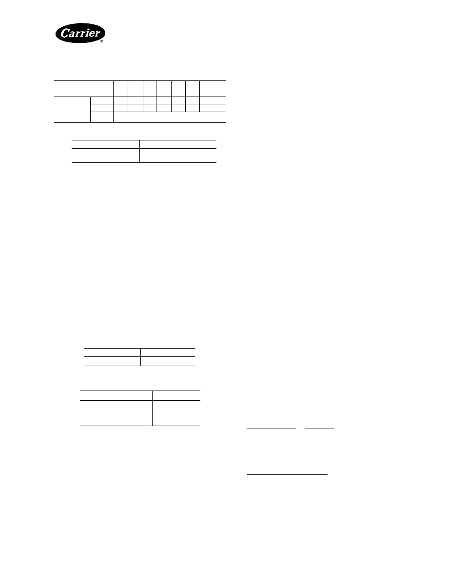
Table 7 — Actual Suction Gas
Temperature Limits (F), R-12, R-22, R-502
SAT. SUCT
TEMP (F)
-60
-50
-40
-30
-20
-10
Oto 50
ACTUAL
SUCTION
GAS
TEMP(F)
R-12
—
—
35
45
55
65
65
R-502
25
35
45
55
65
75
75
R-22
See Note 1
NOTES:
1 For continuous operation with R-22
SAT. SUCT TEMP (F)
MAX. SUPERHEAT (F)
-40 to 40
25
40 to 50
15
2 Do not operate unloaders at saturated suction temperatures
at or below 0°F without prior approval from Carrier/Carlyle
Engineering
3. The compressor operates fully unloaded for prolonged
periods. Under these conditions, suction gas levels
may not suffice to remove the heat of compression
and friction. This condition can occur in any applica
tion, but is most likely in low-temperature systems or
variable-volume applications that use hot-gas bypass
to maintain specified conditions under low evaporator
load. Refer to 5F,H Application Data for additional
information.
Adjust water flow through oil cooler to maintain
crankcase return oil temperature at 100 to 120 F. Crank
case temperature must remain below 140 F; shaft seal
temperature at the seal housing should not exceed 170 F.
Tables 8 and 9 list maximum working pressures for
oil and water and estimated water flow rates for various
oil
cooler/compressor
combinations.
For
additional
information,
see
Accessory
Oil
Cooler
Installation
Instructions.
Table 8 — Oil Cooler Maximum Working Pressure
OIL
150 psig
WATER
150 psig
Table 9 — Oil Cooler Estimated Water Flow Rates
COMPRESSOR
GPM*
5F
’/4-1
5H40-66
1-2
5H80,86
1
'/2 -
3
5H120.126
2-4
*Flow rate based on 80 F entering water.
Check Water-Cooled Heads — To prevent oil
breakdown and sludge formation, the discharge gas
temperature must remain below 275 F. Water-cooled
cylinder heads are available as an accessory for this
purpose. See Accessory Water-Cooled Head Package
Installation Instructions for additional information.
SERVICE INSTRUCTIONS
Service and repair of Carrier reciprocating com
pressors and other refrigeration components should be
performed only by fully trained and qualified personnel.
Service Notes
1. Compressor components are shown in normal order
of removal from compressor (Fig. 21 and 22).
2. For replacement items, use Carrier specified parts.
See Carrier 5F,H Specified Parts list for compressor
part interchangeability.
3. Before servicing compressor, pump down the refrig
erant as follows:
a.
Start compressor, close suction service valve,
and reduce crankcase pressure to 2 psig. (Bypass
low pressurestat with jumper.)
b. Stop compressor; close discharge service valve to
isolate it from system.
c.
Bleed any residual refrigerant. Drain oil if
neeessary.
4. After disassembly, clean all parts with solvent. Use
mineral spirits, white gasoline or naphtha.
5. Before assembly, coat all parts with compressor oil
and clean and inspect all gasket surfaces. Replace all
gaskets with new, factory-made gaskets, and lightly
coat with oil. See Table 10 for torque values.
6.
After reassembly, evacuate compressor and open
suction and discharge valves. Restart compressor
and adjust refrigerant charge.
Lubrication System
OIL PUMP (For 5H120 and 126 compressors, manu
factured in 1969 or later, refer to Gear Rotor Type
Oil Pump.)
Drain oil below level of pump-end bearing head.
Remove bearing head. Complete end bell assembly must
be removed on 5H40, 46, 60, 66, 80 and 86 models. Check
oil-pump rotor for end play. Maximum allowable move
ment of rotor is 0.0025 in. (Table 11). If there is excessive
end play, reposition oil-pump bushing in bearing head as
described below.
Turn rotor; if there is more than a slight drag, remove
pump cover and disassemble oil pump. Check all parts
(Fig. 20, 23 and 24) for wear and damage. Inspect oil-
pump bushing for scoring. Replace hushing if scored. If
bearing head is scored, replace complete bearing head and
oil-pump assembly.
Oil-Pump Bushing Installation — Position bushing oil
groove at top when the bearing head is installed.
Machined
cireumferential
lines
mark
the
lead,
or
entering, end of the bushing. Press new bushing into the
pump-end bearing head from the inner side of the head
(Fig. 25 and 26).
Oil Pump Bushing Positioning (Fig. 25 and 26)
1. Place 0.001-in. cireular, field-fabricated shim against
bushing and install pump. (Shim between bushing and
oil pump rotor.)
(Continued on page 25.)
Manufacturer reserves the right to discontinue, or change at any time, specifications or designs without notice and without incurring obligations.
Book
Tab
PC 111
Catalog No 530-526
2a
PrintedinUSA
Form5F,H-11SI
Pg 19
For replacement items use Carrier Specified Parts
2-86
Replaces: 5F,H-9SI