Crankshaft inspection and service, 5f,h open-drive compressors – Carrier 5F User Manual
Page 32
Attention! The text in this document has been recognized automatically. To view the original document, you can use the "Original mode".
HEATING A COOLING
5F,H
Open-Drive Compressors
CAPACITY
CONTROL
VALVE
SURGE
DRUM
TO UNLOADER
L
----------
POWER ELEMENTS
^ UNLOADER
^
IvJSEQUENCE
tf* HYDRAULIC
V RELAY
(AUXILIARY
CONTROL
VALVE )
FROM COMPR
OIL PUMP
(CONTROL OIL
STRAINER)
ro UNLOADER
POWER ELEMENTS
NOTE Dotted lines indicate piping behind surge drum
Fig. 42 — 5H Pump-End Cover and Control
Assembly (5H40, 46, 60, 66, 80, 86)
CAPACITY CONTROL VALVE
OIL PUMP PRESSURE
(BEFORE FILTERING)
CAPILLARY
TO OIL PUMP
INTAKE
HYDRAULIC
RELAY
' i^vOl^-OIL PUMP PRESSURE
(AFTER FILTERING)
unloader
SEQUENCE
PLUG, MAGNETIC (PUMP INTAKE)
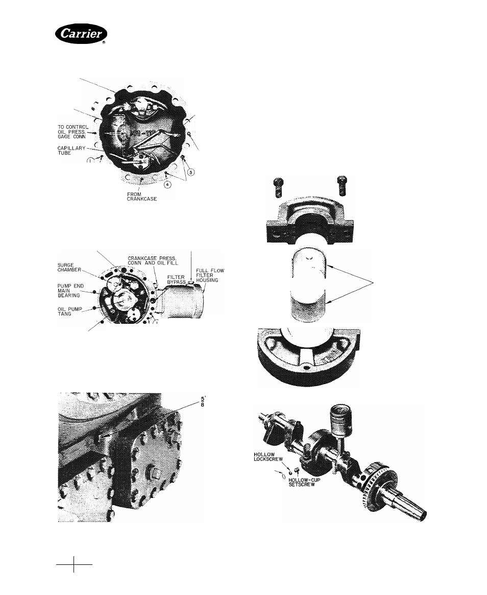
Fig. 43 — 5H120 and 5H126 Pump-End
Bearing Head
Crankshaft Inspection and Service
DISASSEMBLY — Remove cylinder heads, valve
plates, connecting rod and piston assemblies, and pump-
end main bearing head.
On 5H80, 86, 120 and 126 units, remove hollow-center
main bearing lock screw located beneath plug (Fig. 44)
and loosen hollow-cup setscrew (Fig. 45) until center
main bearing can be slid from its support. On 5H86, 120
and 126 units, disconnect oil line to center main bearing.
Remove crankshaft through pump-end opening.
Normally it is not necessary to remove the oil separator
impeller (Fig. 29) from the 5H120 or 126 shaft. If impeller
must be removed for any reason, however, immerse it in
BEARING INSERTS
ACCESS
PLUG
Fig. 44 — 5H80, 86,120,126 Center Main Bearing
Housing Setscrew Location
GASKET
PLUG-;C|^
Fig. 45 — Center Main Bearing
(5H120 and 5H126)
Manufacturer reserves the right to discontinue, or change at any time, specifications or designs without notice and without incurring obligations.
Book
2
PC111
Catalog No 530-526 Printed inUS A Form5F,H-11SI
Pg 32
2-86
Replaces: 5F,H-9SI
Tab
2a
For replacement items use Carrier Specified Parts