5f,h open-drive compressors – Carrier 5F User Manual
Page 18
Attention! The text in this document has been recognized automatically. To view the original document, you can use the "Original mode".
HEATING A COOLING
5F,H
Open-Drive Compressors
OIL
FILTER'
HOUSING
SHUTOFF VALVES
PLAIN
ELBOW
(PART
NO DDI0CA052)
-ORIFICE ELBOW (PART NO
DD40CA05I)
Fig. 19 — Oil Filter Accessory Package
(5H40 through 5H86)
CHECK OIL AND SHAFT SEAL TEMPERATURE
— The normal operating temperature of the oil in the
crankcase ranges from 100 F to 135 F when fully loaded.
Do not permit maximum oil temperature to exceed 150 F.
Conditions under which such excessive temperatures
could occur include situations where the compressor
operates in a fully unloaded condition for an extended
period, because the compressor would not be able to
remove all of the heat generated by compression and
friction. In such situations, use an oil cooler to maintain
safe operating temperatures. Refer to 5F,H Application
Data for more information.
When crankcase oil temperature falls within the 120
to 135 F range, the shaft seal housing temperature should
be approximately 140 to 150 F. Shaft seal housing tem
peratures above 170 F may cause shaft seal to age rapidly,
and harden and crack. Therefore:
If shaft seal housing temperature exceeds 170 F,
STOP THE COMPRESSOR. DO NOT restart until
the cause of overheating has been identified, and
the condition corrected.
OIL COOLER USAGE — The accessory oil cooler
maintains safe operating oil temperatures when:
1. The suction gas becomes highly superheated (Table 7).
2. a. The compression ratio exceeds 5:1 on R-22
systems,
b. Application data indicates the need for an oil cooler
for R-12 and R-502 systems. This is especially
likely in increased displacement compressors such
as the 5H46, 66, 86 and 126. The compression ratio
can be determined from the following formula:
Compression _ Absolute Discharge Pressure
Ratio
Absolute Suction Pressure
t
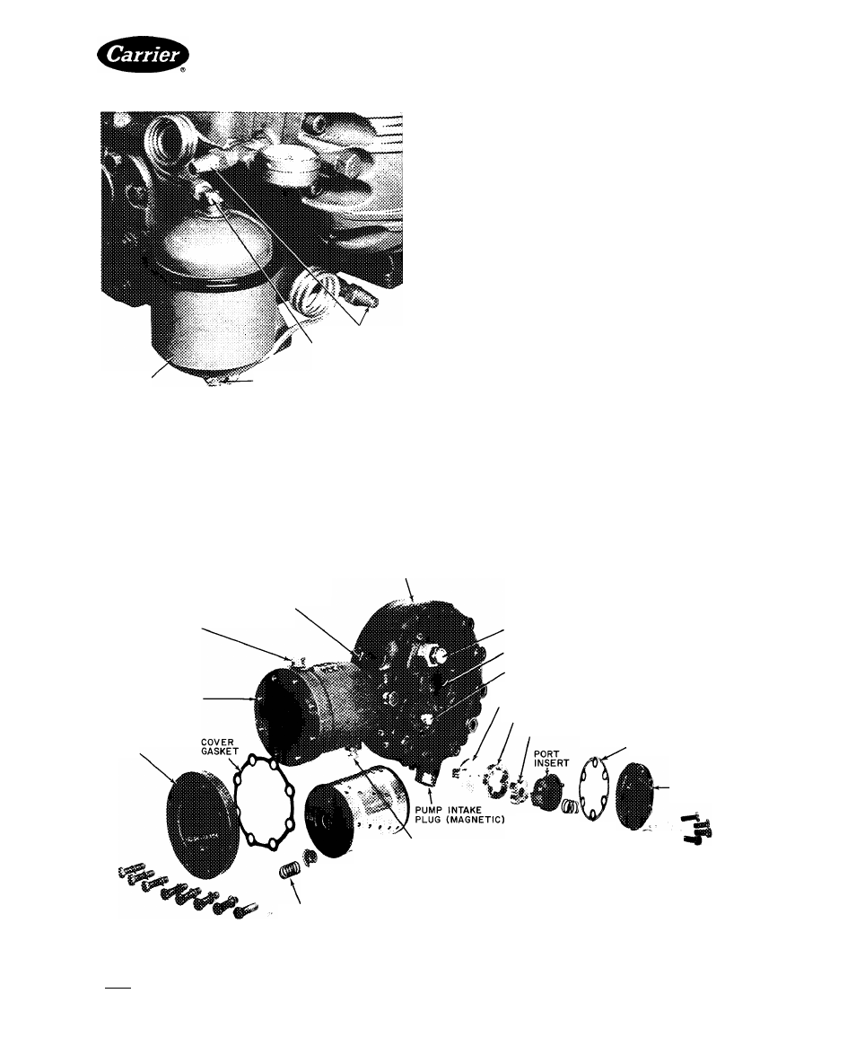
PUMP END BEARING HEAD
OIL FILL PLUG
OIL
PRESS
6AGE
CONN
(BEFORE FILTER )
OIL FILTER HOUSING
OIL
FILTER
COVER
CAPACITY
CONTROL
VALVE
ADJUSTING
STEM
BUSHING LOC
CONTROL OIL PRESS. GAGE CONN
DRIVE DISC
OUTER GEAR
INNER GEAR
COVER GASKET
OIL PUMP COVER
SPRING
OIL PRESS. GAGE CONN (AFTER FILTER)
OIL FILTER
SPRING RETAINER
OIL FILTER SPRING
Fig. 20 — Oil Pump and Filter Assembly (5H120, 126)
m'
Manufacturer reserves the right to discontinue, or change at any time, specifications or designs without notice and without Incurring obligations.
Book[2
PC111
Catalog No 530-526
PrIntedInUSA
Form5F,H-11SI
Pg 18
2-86
Replaces: 5F,H-9SI
Tab 2a
For replacement items use Carrier Specified Parts