Pump-end main bearing (fig. 46), Pump-end main bearing, 5f,h open-drive compressors – Carrier 5F User Manual
Page 33
Attention! The text in this document has been recognized automatically. To view the original document, you can use the "Original mode".
HEATING A COOLING
5F,H
Open-Drive Compressors
hot water or oil until heated to 180F or more. Remove
all traces of water before reassembly. Do not heat
impellers with torch.
INSPECTION — Check crankshaft journals for wear
and tolerances (Table 11). Remove crankshaft plugs,
check oil passages and clean if clogged.
Connecting-rod bearing inserts and main bearings are
available for crankshafts reground from .010-in. or
.020-in. undersize. A worn crankshaft suitable for
regrinding to above tolerances can be exchanged for a
factory-reground
crankshaft
and
bearings.
Factory-
reground crankshafts are stamped on both ends with an
A (.010-in. undersized) or B (.020-in. undersized).
IMPORTANT; Do NOT regrind crankshafts for
5H46, 66, 86, and 126 compressors in the field.
Replace shafts with scored journals.
All instructions for field grinding apply only to
standard-stroke crankshafts.
On crankshafts reground locally, hold throw to
1.001 in. for 5F compressors and to 1.376 in. on 5H com
pressors. Stamp A or B on crankshaft and pump-end
bearing head next to oil pressure gage connection.
To
determine
maximum
and
minimum
journal
diameters for undersized shafts, subtract the amount (in.)
that the shaft will be ground undersize from factory from
the tolerances specified in Table 11. For example, the
factory tolerance for 5H40 seal-end journal is 2.6225 in.
to 2.6235 inches. Tolerance for a crankshaft reground
to .010 in. undersize should therefore be held between
2.6125 in. and 2.6135 inches.
IMPORTANT:
When
regrinding
the
seal-end
journal on 5H120 crankshaft, do not grind in the
area of the oil separator impeller. This is not journal
area, and must remain intact or the oil separator
impeller will not fit properly.
REASSEMBLY — If 5H120 or 5H126 oil separator has
been removed, read impeller paragraph below before
installing crankshaft.
When regrinding crankshaft, remove crankshaft plugs
and clean oil passages as well. Before replacing crank
shaft, insert and tighten plugs, and reinstall the 5H120
and 126 oil separator impeller:
1. Insert dowel key (Fig. 29) with axis parallel to axis
of crankshaft. Position key so chamfered edge is
toward radius of crankshaft journal.
2. Immerse oil separator impeller in oil or hot water to
heat it to 180 F or more. If water is used, remove all
traces before reassembly. Install impeller on crank
shaft with dowel key lined up with impeller keyway.
Impeller must fit key snugly.
3. Check that seal-end thrust washer is in place on dowel
key in crankcase.
Insert crankshaft and install pump-end bearing head,
connecting rod and piston assemblies, valve plate and
cylinder heads. On 5H80, 86, 120 and 126 units, insert
center main bearing setscrew and lock screw as described
under Servicing Center Main Bearing. On 5H86, 120 and
126 units, reconnect oil line to center main bearing.
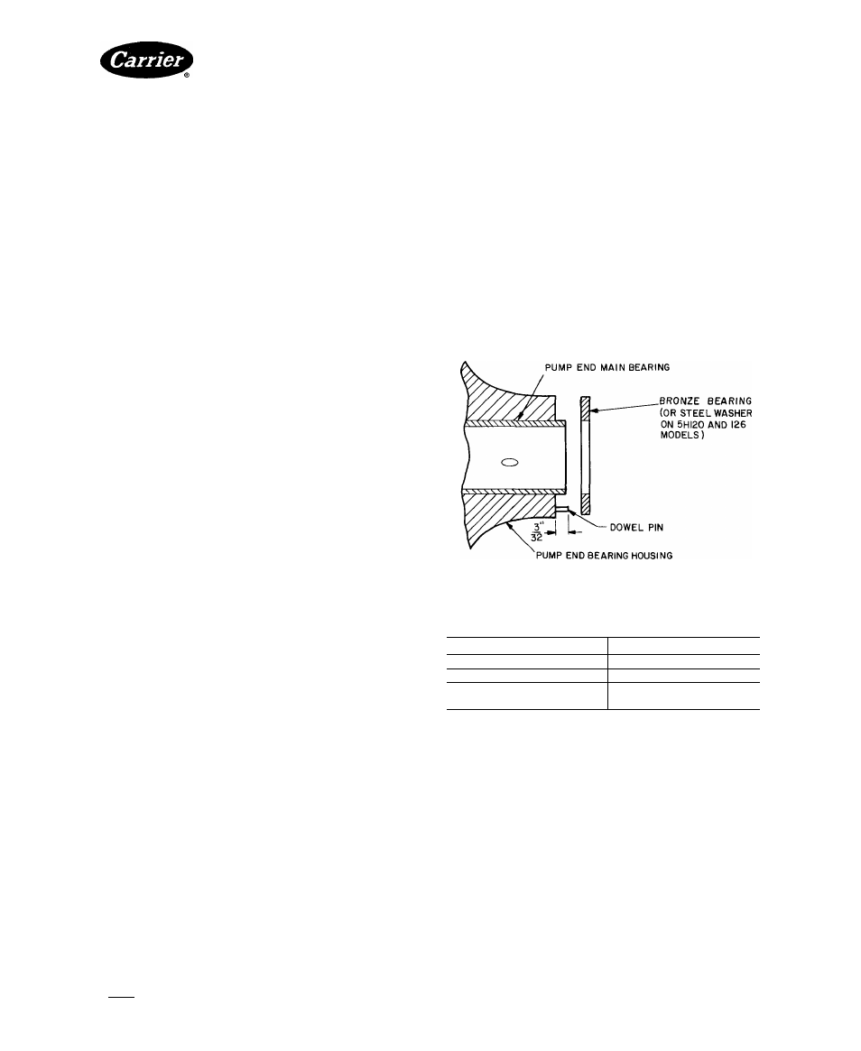
Pump-End Main Bearing (Fig. 46)
DISASSEMBLY AND INSPECTION — On 5H40, 46,
60, 66, 80 and 86 units, remove pump-end cover. Remove
pump-end bearing head on all units. Inspect bearing for
tolerances shown in Table 11. If a pump-end main bear
ing is worn, remove bronze bearing washer, and chisel out
bearing. Inspect bearing housing for wear (Table 11) and
damage. Remove any burrs.
REASSEMBLY
1. Lubricate outside of new bearing with heavy grease.
2. Line up hole in bearing with oil port in housing.
3.
Press bearing into place using a puller shoulder
(Table 12and Fig.47 and 48) andjack screw or bearing
press.
Place bearing washer on bearing with notch in washer
properly positioned around dowel pin (Fig. 46).
4.
Fig. 46 — Pump-End Main Bearing Position
Table 12 — Main Bearing Puller Sizes
COMPRESSOR
PULLER SIZE
5F20, 5F30
5F20
5F40, 5F60
5F40
5H40,46,60,66,
80,86,120,126
5H40
NOTES.
1. Bearing pullers are available from the Robin Air Mfg Co,
Montpelier, Ohio
2. Side of puller marked B is for undersized bearings.
Center Main Bearing — Size 5H80 through 5H126
compressors have a center main bearing and housing.
DISASSEMBLY AND INSPECTION — On 5H86, 120
and 126 compressors, disconnect oil line to center main
bearing. (5H80 center main bearings are fed through the
shaft.)
Remove plug on compressor crankcase (Fig. 44).
Then remove hollow lock screw beneath the plug (Fig.
45). Next, loosen hollow-cup setscrew until center main
bearing assembly can be slid from its support. Remove
crankshaft and bearing assembly.
Disassemble bearing (Fig. 45) and inspect for proper
tolerances (Table 11).
Manufacturer reserves the right to discontinue, or change at any time, specifications or designs without notice and without incurring obligations.
Book|2
PC 111
Catalog No 530-526
PrintedinUSA
Form5F.H-11SI
Pg 33
2-86
Replaces; 5F.H-9SI
For replacement Items use Carrier Specified Parts.
Tab 2a