Capacity control inspection and service, 5f,h open-drive compressors – Carrier 5F User Manual
Page 31
Attention! The text in this document has been recognized automatically. To view the original document, you can use the "Original mode".
HEATING A COOLING
5F,H
Open-Drive Compressors
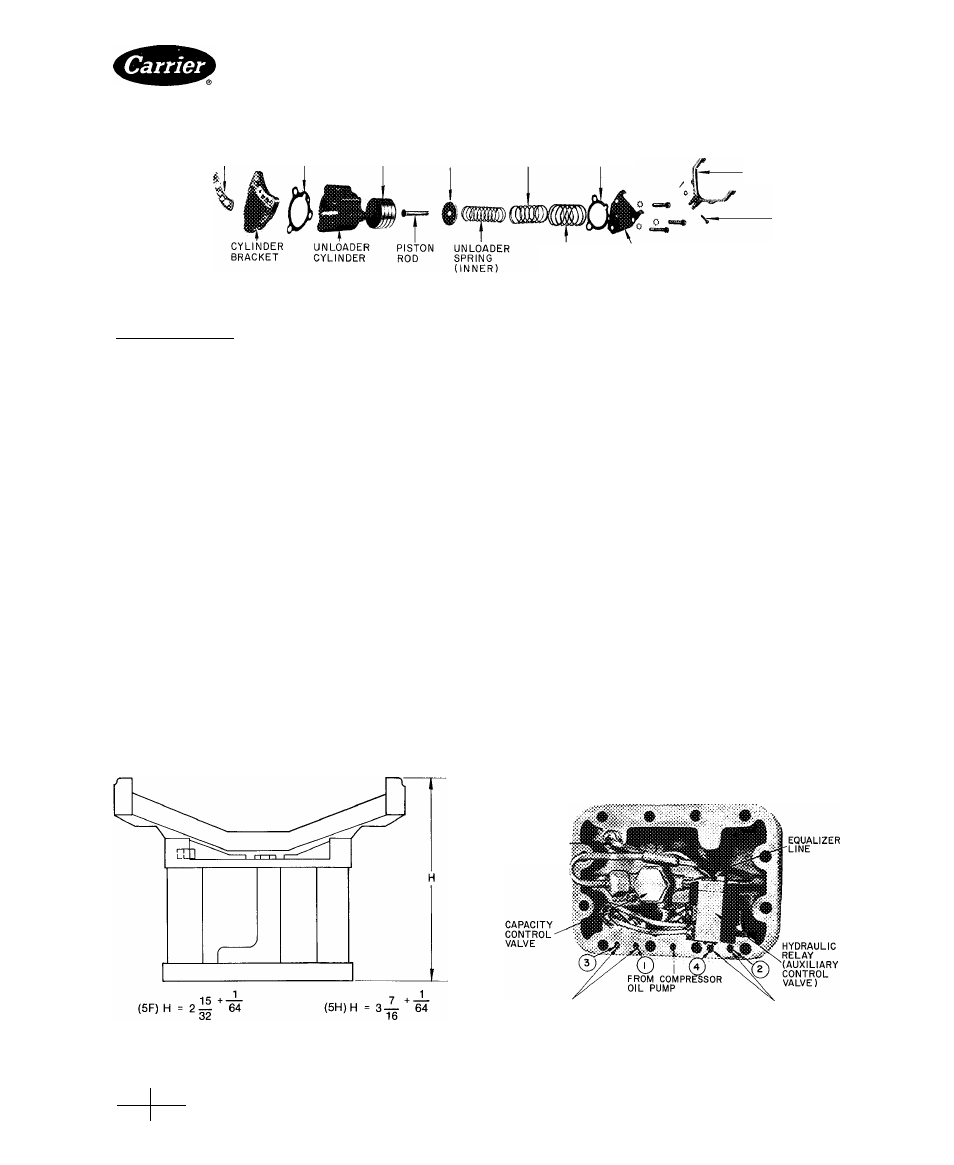
UNLOADER
CYLINDER
BRACKET
GASKET
GASKET
(BOTTOM)
SPRING
RETAINER
PISTON WASHER
UNLOADER
CYLINDER
SPRING
GASKET
(MIDDLE)
(TOP)
UNLOADER
SPRING
(OUTER)
CYLINDER
COVER PLATE
Fig. 39 — Unloader Power Element (Typical)
UNLOADER FORK
CLEVIS PIN
Unloaded Operation — A drop in suction pressure
decreases pressure against control valve bellows. Range
adjustment spring presses against the push pins, com
pressing the valve spring. This moves the needle valve
off the seat.
Control oil bleeds from hydraulic relay and control
valve to crankcase, relieving oil pressure on hydraulic
piston. The piston retracts, preventing transmission of
pressurized oil to controlled cylinder power element(s),
and the oil drains to crankcase.
As oil pump pressure on power element drops, the
piston moves downward. Lifting fork(s) pivot(s) upward,
moving lifting pins upward; suction valves rise from
their seats and controlled cylinder(s) unload(s). It should
be noted that a minimum of 33 to 35 pounds of oil pres
sure is required for proper unloader operation.
Capacity Control Inspection and Service
UNLOADER POWER ELEMENT REMOVAL
Remove cylinder head, valve plate, connecting rod,
piston and cylinder sleeve. Remove Allen head cap
screws (2) holding unloader power element in position.
Remove power element (Fig. 39) and disassemble.
Check all parts for wear or damage.
POWER
ELEMENT
REPLACEMENT
Check
un
loader fork height (Fig. 40) of new or assembled power
element.
Attach power element to internal suction manifold.
Replace cylinder sleeve piston, connecting rod, valve
plate, cylinder head and handhole cover.
EXTERNAL ADJUSTING STEM REMOVAL does
not require compressor to be pumped down. Loosen hex
nut at valve stem base and remove adjusting stem
assembly.
REMOVAL
OF
CAPACITY
CONTROL
VALVE
AND HYDRAULIC RELAY — Assembly is located
in handhole cover (Fig. 41) of 5F40 and 5F60 units;
in pump-end cover (Fig. 42) of 5H40, 46, 60, 66, 80,
and 86 units; and in pump-end bearing head (Fig. 43) of
5H120 and 126 units.
Remove capacity control valve and hydraulic relay.
NOTE; It is not practical to remove hydraulic relay from
5H40 through 5H86 compressors.
Inspect parts for wear, damage or evidence of leaking
or sticking.
A new handhole cover, pump-end cover or pump-end
bearing head with control valve assembly and hydraulic
relay may be installed. However, capacity control valve
(and hydraulic relay on 5H120 and 126 units) is available
as a separate parts item for installation on original
handhole cover, pump-end cover, or pump-end bearing
head.
INSPECT CONTROL OIL STRAINER — On 5F com
pressors, the control oil strainer is located on the side
of the pump-end bearing head (Fig. 23). Strainer is
located behind the control oil pressure gage connection
block on the 5H120 and 126 units (Fig. 20) and on pump-
end cover (Fig. 42) of all other 5H compressors.
Remove strainer and inspect it for holes and dirt. Clean
it with solvent and replace.
TO CONTROL
PRESSURE
GAGE CONN.
TO UNLOADER
POWER ELEMENTS
UNLOADER
WS
TO UNLOADER
POWER ELEMENTS
-
0
-
0
Fig. 40 — Unloader Fork Height (5F and 5H)
SEQUENCE
Fig. 41 — Compressor Handhole Cover and
Assembly (5F40 and 5F60)
Manufacturer reserves the right to discontinue, or change at any time, specifications or designs without notice and without incurring obligations.
Book
2
PC111
Catalog No 530-526 Printed in U S A Form 5F.H-11 SI
Pg 31
2-86 Replaces: 5F,H-9SI
Tab
2a
For replacement Items use Carrier Specified Parts.