5f,h open-drive compressors – Carrier 5F User Manual
Page 30
Attention! The text in this document has been recognized automatically. To view the original document, you can use the "Original mode".
HEATING A COOLING
5F,H
Open-Drive Compressors
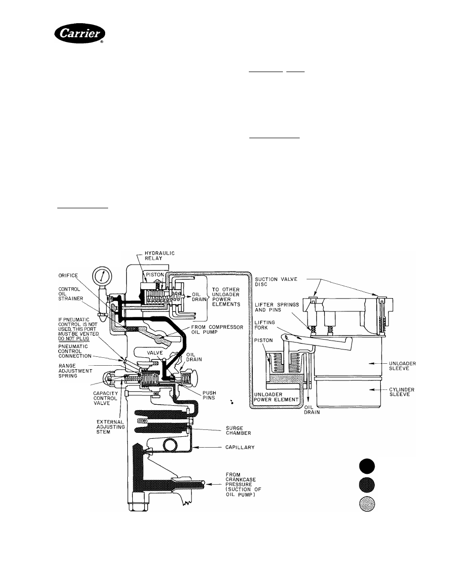
2. A hydraulic relay, which (except on the 5F20 and 30)
feeds oil to the unloader power elements in sequence.
Control oil pressure from the capacity control valve
activates this relay.
3. A hydraulic power element, which supplies the
power
necessary
to
operate
the
valve-lifting
mechanism. It is modulated by the capacity control
valve.
4. A valve-lifting mechanism, whieh consists of a
sleeve, a lifting fork and a push-pin assembly around
each controlled cylinder. The valve-lifting mechanism
holds the suction valve open, or permits the valve to
remain in normal operating position depending on its
actuation by the power element.
These components operate in the following manner:
5F20 AND 30 CAPACITY CONTROL OPERATION
(Fig. 36) (With Optional Unloaders and Control)
Loaded Operation — A rise in suction pressure causes
needle valve to close. Oil pressure in power element
increases as oil enters capacity control circuit from oil
pump. Power element piston is forced upward, pivoting
lifting fork downward. Lifter pins drop, allowing suction
valve to seat and load controlled cylinder.
Unloaded Operation — A drop in suction pressure causes
needle valve to open. Oil bleeds through valve to crank
case, decreasing oil pressure in power element. As oil
pressure to power element drops, the piston moves
downward. Lifting fork pivots upward, moving lifting
pins upward; suction valve rises from its seat and con
trolled eylinder unloads.
5F40
THROUGH
5H126
CAPACITY
CONTROL
OPERATION (Fig. 37 and 38)
Loaded Operation— A rise in suction pressure increases
pressure against capacity control valve bellows, com
pressing range adjustment spring. Compression of range
adjustment spring allows valve spring to move push pins
and valve needle point toward valve seat. Flow of control
oil to crankcase through oil drain is throttled.
Control oil pressure rises as oil enters capacity control
circuit through orifice from compressor oil pump circuit.
Increased control oil pressure advances hydraulic relay
piston (against spring) which feeds oil at full pressure to
one or more controlled cylinder power elements depend
ing on position of control valve.
Pump oil pressure in unloader power elements forces
piston upward, pivoting the lifting fork(s) downward.
Lifter pins drop, allowing suction valve(s) to seat and load
cylinder(s).
CONTROL
OIL
PRESSURE
TRAVELING
NUT
CONTROL
OIL
PRESSURE
CRANKCASE
PRESSURE
OIL
PUMP
PRESSURE
Fig. 38 — Capacity Control (5H120, 5H126)
Manufacturer reserves the right to discontinue, or change at any time, specifications or designs without notice and without incurring obiigations.
Book|2
PC111
Catalog No 530-526
Printed In U S A
Form5F,H-11SI
Pg 30
2-86
Replaces: 5F,H-9SI
For replacement items use Carrier Specified Parts.
Tab 2a