A warning, 5f,h open-drive compressors – Carrier 5F User Manual
Page 25
Attention! The text in this document has been recognized automatically. To view the original document, you can use the "Original mode".
HKATING ft COOLING
5F,H
Open-Drive Compressors
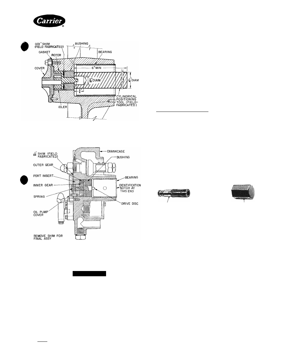
Fig. 25 — Setting Oil Pump Bushing
(Typical 5F20 through 5H86 —
5H40 Bearing Head Shown)
Fig. 26 — Setting Oil Pump Bushing
(Typical 5H120, 126)
2. Complete assembly of oil pump.
A
WARNING
Oil pump assembly must be flush with coverplate
surface, but must not protrude beyond bearing
head surface.
3. Tap bushing with a cylindrical positioning tool to
seat it against shim (Fig. 25 and 26).
4. Disassemble oil pump and remove shim.
5. Reassemble oil pump; check for binding.
6. Install bearing head on compressor. Line up tang on
oil-pump rotor shaft with slot in end of crankshaft.
Check oil pump for proper direction of rotation.
1. Refill compressor oil to proper level.
Observe oil pressure when starting compressor. If
correct pressure (Table 4) is not reached in 8 to 12
seconds, stop compressor and recheck oil pump.
GEAR ROTOR TYPE OIL PUMP (Models 5H120 and
126 manufactured from 1969 on) — Remove bearing
head and oil-pump cover (Fig. 20). Disassemble oil pump.
Check all parts for wear and damage. Inspect bushing for
scoring. Replace hushing if scored. If bearing head is
scored, replace complete bearing head and oil-pump
assembly.
Install New Oil-Pump Bushing — Reinstall oil pump into
bearing head with 1 / 64-in. shim between port insert and
oil-pump cover. Install oil-pump cover without gasket for
this operation. Press new bushing into bearing head from
inner side so that the bushing oil groove is at the top
when the bearing head is installed (similar to Fig. 26).
Machined circumferential lines mark the lead, or enter
ing, end of the bushing. Press on bushing until port insert
bottoms against the 1/64-in. shim. Remove pump cover
and shim. Reinstall pump cover with gasket and install
assembled bearing head on compressor. Check oil pump
for proper direction of rotation.
OIL PRESSURE REGULATING VALVE (nonadjust-
able, Fig. 27) is located on the side of compressor adjacent
to seal housing. Regulator maintains correct oil pressure
(Table 6) and ensures satisfactory unloader operation.
A.
OIL
REGULATING
VALVE BODY
GASKET
OIL
REGULATING
VALVE CAP
Fig. 27 — Oil Pressure Regulating Valve
(Nonadjustable)
Unscrew regulator from crankcase; use 5/ 16-in. Allen
wrench on all compressors except 5H120, which requires
1/2-in. Allen wrench. Regulator must not be clogged and
plunger must not be stuck. Check drillings to regulator
for fouling.
The nonadjustable oil pressure regulator is inter
changeable on all current 5F,H compressors except
5 H120 and 5 H126 models. 5 H120 and 5 H126 units have
larger,
nonadjustable
regulators.
Early
5F,H
com
pressors were equipped with an adjustable-type oil-
pressure regulator. When an adjustable-type regulating
valve needs replacing, use a nonadjustable regulator.
OIL RETURN CHECK VALVE (5F20 through 5H86)
allows oil to return from suction manifold to crankcase.
This normally open valve closes when crankcase pressure
becomes higher than suction pressure (Fig. 28).
Two disc-type check valves on 5F20 and 5F30 com
pressors are located beneath partition between suction
manifold and crankcase, one on each side of compressor.
Remove check valves through bottom cover or pump
end of eompressor.
Manufacturer reserves the right to discontinue, or change at any lime, specifications or designs without notice and without incurring obligations.
Book|2
PC 111
Catalog No 530-526
PrIntedInUSA
Form5F,H-11SI
Pg 25
2-86
Replaces: 5F.H-9SI
For replacement items use Carrier Specified Parts.
Tab 2a