A caution, 5f,h open-drive compressors – Carrier 5F User Manual
Page 11
Attention! The text in this document has been recognized automatically. To view the original document, you can use the "Original mode".
HEATING A COOLING
5F,H
Open-Drive Compressors
#
Step 5 — Install Multiple Compressors
EQUALIZING LINES — Compressors operating in
parallel require interconnecting lines for oil and gas
pressure equalization. Special handhole cover plates,
equipped with tapped holes for equalizing lines, are avail
able as options for sizes 5F40 and 5F60, as well as for
sizes 5H40, 46, 60, 66, 80, and 86 eompressors (Fig. 11).
An oil float system is an acceptable alternative to
equalizer lines.
5H120 and 126 Compressors include factory-supplied,
tapped cover plate. On these compressors, use only
lower connection for oil equalization (Fig. 11). Connect
gas equalizing line to flange connection shown. Mat
ing flange for 1-1/8 in. line is Carrier Part No.
DK24CA712 (Mueller Part No. A-5151); gasket Part No.
is DK29GA005 (Mueller Part No. A-5152).
GAS
EQUALIZER
CONNECTION
i
4"
od
flange
(5HI20-I26 ONLY!
OIL EQUALIZER
connection
l" IPS
GAS EQUALIZE
connection
Fig. 11 — Special Handhole Cover and
Equalizer Connections (Typical)
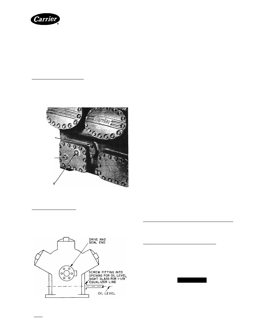
5F20 and 30 Compressors have no special tapped cover
plate. Use opening for oil sight glass to attach the I -1 / 8 in.
line for gas and oil equalization (Fig. 12). Accessory
Package No. 06DA900072 provides two I/8-in. line
adapters to thread into the sight glass opening. If addi
tional equalization is desired, run a 3/8-in. line to the oil-
filter plug connection (Fig. I and 2).
Fig. 12 — Equalizer Connections (5F20 and 5F30)
Step 6 — Make Electrical Connections
GENERAL NOTES
1. Factory wiring complies with National Electrical Code
(NEC). Any field modifications or additions must
comply with all applicable codes.
2. *For control circuit information, refer to Accessory
Control Panel Installation Instructions.
3. If control circuit power is supplied from a separate
source, rather than from a transformer, bring 115-v
power through a field-supplied, 15-amp disconnect,
in compliance with NEC Section 440-14 (disconnect
must be in sight from and readily accessible from
unit).
4. Open control-power disconnect only when servicing
unit.
Crankcase
heaters
must
remain
energized
when unit is not operating.
5. *Factory wiring is for single pumpout control. Do not
use pumpout control on equipment used with DX
coolers. Wiring label shows field connections used
with DX cooler.
6. *Contactor C2 is used with 208-v motors, 25 through
60 hp, and 460-v motors, 50 through 150 hp.
7.
*When field interlocks are used, remove jumpers
between terminals 3 and 4, and between terminals
7 and 8 on TB2.
♦Refers to compressor units and condensing units only.
ATTACH
POWER
WIRES
TO
COMPRESSOR
MOTOR — Attach power wires in accordance with
motor manufacturer’s instructions and in compliance
with NEC and applicable local codes.
CHECK MOTOR ROTATION — Before connecting
motor to compressor, check direction of motor rotation.
Rotation must be in same direction as that indicated by
arrow on compressor pump cover (or on plate attached
near pump-end bearing housing). If direction is not the
same, reverse motor rotation by reversing any 2 power
leads to motor.
If rotation of oil pump is reversed, reverse direction of
pump rotation arrow as well. At that time make the
following adjustments:
All 5F Compressors and 5H120and 126 Compressors —
Remove 6 cap screws from oil pump cover (Fig. 1-4, 8).
Do not damage gasket. Rotate cover 180 degrees and
replace. Arrow at top of oil cover will indicate new direc
tion of rotation.
5F40, 46, 60. 66. 80 and 86 Compressors — Drain oil
below level of pump-end dome cover (Fig. 5-7). Remove
pump-end cover to expose oil pump cover in center of
main bearing housing. Rotate oil pump cover 180 degrees
and replace it. Replace pump-end cover and reverse
external arrow to match new direction of rotation. Proper
direction can later be checked without removing pump-
end cover.
A CAUTION
If the special gasket between oil pump cover and
oil pump is damaged, replace with correct gasket
only. Check oil pressure immediately after starting
compressor.
Manufacturer reserves the right to discontinue, or change at any time, specifications or designs without notice and without incurring obiigations.
BookI 2
PC 111
Catalog No 530-526
PrintedinUSA
Form5F,H-11SI
Pgll
2-86
Replaces: 5F.H-9SI
For replacement items use Carrier Specitled Parts
Tab 2a