A caution, Cylinder head and valve assemblies, Cylinder and unloader sleeves – Carrier 5F User Manual
Page 27: 5f,h open-drive compressors
Attention! The text in this document has been recognized automatically. To view the original document, you can use the "Original mode".
HEATING A COOLING
5F,H
Open-Drive Compressors
detachable suction manifold and suction line. Withdraw
2 suction strainers.
Clean strainer with solvent or replace if broken or
corroded. When replacing suction strainer, do not
damage it.
On 5H120 and 126 compressors, positioned manifold
cover plate must compress strainer bail. If bail is too
short, grasp on sides and elongate it enough to be com
pressed by manifold cover. Position bail between the 2
bosses on inside of manifold cover to prevent strainer
from turning.
A
CAUTION
If a felt sock filter is installed, remove and inspect it
after 50 hours of operation. Clean filter if required
and replace it for another 50 hours. Clean the suction
strainer whenever the felt sock is removed. Remove
sock when system is clean. (Not applicable for 5F20
and 30 compressors.)
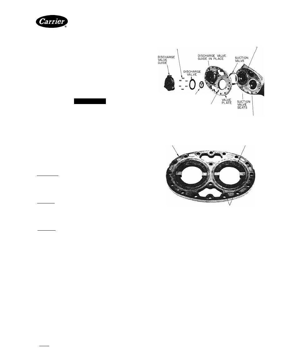
DISCHARGE VALVE
SPRING
VALVE LIFTER
SPRING-
DISCHARGE VALVE
INNER SEAT
DISCHARGE VALVE
OUTER SEAT
SUCTION VALVE
IN PLACE
Fig. 32 — Suction and Discharge Valve Assembly
Cylinder Head and Valve Assemblies
CYLINDER HEAD INSPECTION — Remove cylinder
heads and check heads for warping, cracks and damage
to gasket surfaces.
VALVE INSPECTION (Fig. 32)
Disassembly — Remove cylinder head. Loosen cap
screws holding discharge valve seat to discharge valve
guide, and cap screws holding valve guide to valve plate.
Remove cap screws holding valve plate to cylinder block.
Remove valve plate from cylinder block and discharge
valve guide from valve plate.
Inspeetion — Inspect suction and discharge valve discs
and valve seats for craeks or excessive wear (Table 11).
Check cylinder-sleeve valve stops for uneven wear.
Replace valves if cracked or worn. If valve seats are worn,
replace complete valve plate assembly. If cylinder-sleeve
valve stops are worn, replace sleeve.
Reassembly — Pistons must be below tops of cylinder
sleeves. To position correctly, turn crankshaft or force
pistons down.
1. Place suetion valve springs in valve plate recesses.
Large
spring
coil
should
be
in
full
contact
with bottom of recess.
2. Place suction valve disc on valve springs; press disc
into valve plate recess. Slide valve retainer elips into
place (Fig. 33). Clips must not cover valve lifter
springs or pins. Valve retainer clips 5F20-2061 (5F
compressors) and 5H40-2061 (5H eompressors) are
field supplied.
3. Bolt valve plate to cylinder block. Remove valve elips.
4. Place discharge valve springs in diseharge valve guide
spring recesses.
5. Place diseharge valve dise over springs, and fit inner
spring in place over valve disc. Hand-tighten bolts
holding inner seat to valve guide (valve guide
assembly).
6. Place valve guide assembly on valve plate. Tighten all
bolts and bend tabs on lock washer and lock plates.
Replace cylinder head.
VALVE PLATE
SUCTION VALVE DISC
SUCTION VALVE RETAINER CLIPS
Fig. 33 — Valve Clips in Place
Cylinder and Unloader Sleeves
DISASSEMBLY (Fig. 35) — Remove cylinder head,
suction and discharge valve assembly, and pump-end
bearing head. Whenever cylinder sleeve or valve plate is
replaced, use a new suction valve disc.
1. Turn crankshaft until piston is in midposition.
2. Insert a sleeve puller into cylinder and push it down
onto top of piston.
3. Tighten nut on top of sleeve puller to expand puller
in sleeve.
4. Turn crankshaft, forcing sleeve upward until it can
be removed.
5. Remove unloader snap rings (5H eompressors only).
Disassemble unloader sleeve, pins and springs.
INSPECTION — Examine bore of sleeve for wear.
Check suction valve seats for scratches and wear. Check
unloader sleeves, pins and springs for wear and freedom
of movement (Table 11).
REASSEMBLY — When new rings are being installed in
a used cylinder sleeve, break the hard, glazed surfaee
of eylinder sleeve to reduce wearing-in period of new
rings. Clean sleeves thoroughly after breaking glaze.
Manufacturer reserves the right to discontinue, or change at any time, specifications or designs without notice and without incurring obligations.
BookI 2
PC111
Catalog No 530-526
Printed in U.S A.
Form5F,H-11SI
Pg 27
2-86
Repiaces: 5F,H-9SI
Tab
I
2a
For replacement items use Carrier Specified Parts.